This thread has been locked.

If you have a related question, please click the "Ask a related question" button in the top right corner. The newly created question will be automatically linked to this question.

IWR1443BOOST: App note for Digital Front End available for IWR1443?

Part Number: IWR1443BOOST
Other Parts Discussed in Thread: IWR1443, AWR1642, AWR1243

Hi,

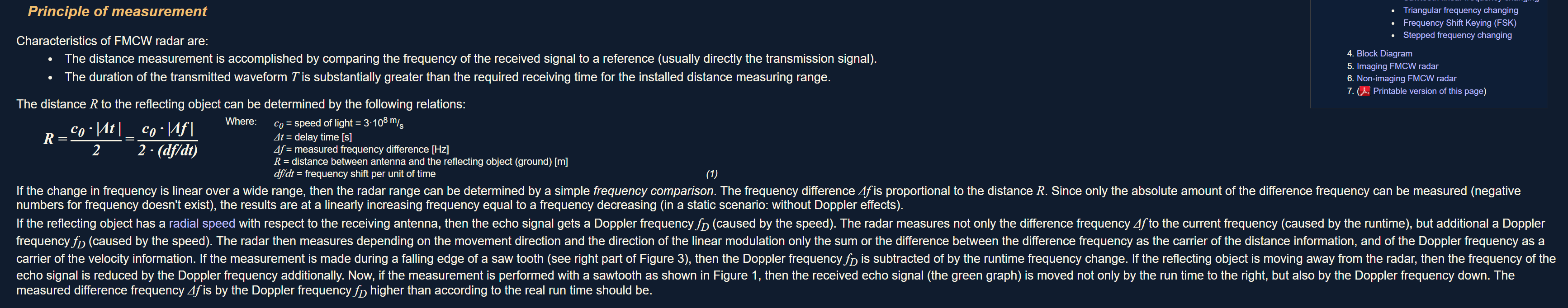
My customer is reading the following whitepaper to understand complex architecture of RF and Digital Front End.

http://www.ti.com/lit/wp/spyy007/spyy007.pdf

Now they are asking the benefit and mechanism of complex based arch. For example
1) distance detection could be 2x better compared to real based arch (detectable 2x far distance in complex mode compared with real only mode)?
   --> I run my eyes through the document, but to me, their understanding is wrong and the benefit of complex based arch looks like description in Table 1. Data rate, MIPS and memory-requirement comparison. Can you comment ? Sorry, I`m new in mmwave.

2) how can I understand the result of "distance FFT" in complex mode ? For example, in case of 1024 point FFT, does it look like :  

- F[-fs/2]=FFT[0]
- F[0]=FFT[512]
- F[fs/2]=FFT[1024]

Also, I found App note "Digital Baseband Architecture in AR1243/AR1642 Automotive Radar Devices"  has been shared in the following post.

IWR1642BOOST: What happes after the processing model is changed from complex 2x to complex 1x in Radar...

e2e.ti.com
Part Number: IWR1642BOOST Hi Champs, Could you please let me know what is different after the processing model is changed from complex 2x to complex 1x in Radar

It seems this is for AWR1243/AWR1642, but do you have IWR1443 specific documentation ? I think it is good for us to understand the digital front end features in complex mode.

Best Regards,
NK

  • swra550.pdfHello,

    The Digital Front End can sample the Mixer output in real or complex mode.  In complex mode, there is a 3db better SNR possible.  The Digital Front End DFE, can process either the real (I only) or complex (quadrature I and Q).    The DFE output is filtered, decimated, and frequency translated based on the DFE mode.  This is explained in the  attached DFE application note.   Signal processing algorithms after DFE can be developed with a complex I and Q style, or with real only I processing.  The DFE mode selection depends on the needs of the signal processing algorithm.

    Real - beat frequency (2 * detected distance) can occur from 0 to real output rate  * .9/2.

    Complex 1x - beat frequency (2 * detected distance) can occur from 0 to .9 * complex output rate

    Complex 2x - beat frequency (2 * detected distance) and interference products can occur from -.45 to .45 * complex output rate

    Note: normally we detect a positive distance, so the negative frequency portion of Complex 2x has signal interference components.

    Regards,

    Joe Quintal

  • Hi Joe,

    Thanks for your reply. Sorry, can you comment on the following question?

    Naoki Kawada said:

    2) how can I understand the result of "distance FFT" in complex mode ? For example, in case of 1024 point FFT, does it look like :

    - F[-fs/2]=FFT[0]
    - F[0]=FFT[512]
    - F[fs/2]=FFT[1024]

    So, if we assume X [m] is the max detectable distance, the corresponding beat frequency and the result of FFT looks like the following in complex 1x mode ?  : 
    - F_beat[-fs/2]=FFT[0] --> 0 [m]
    - F_beat[0]=FFT[512] --> X/2 [m]
    - F_beat[fs/2]=FFT[1024] --> X[m]

    Best Regards,
    NK

  • Hello,

    In the real mode, I only, if I have a sampling rate of x, the sampled signal utilizes 0 to x/2.

    In the complex 1x mode, we have a shifted spectrum, I and Q, if we have a sampling rate of x, the sampled signal can utilize 0 to x

    In the complex 2x mode, we have a complex spectrum, I and Q, if we have a sample rate of x, the sampled signal can utilize -x/2 to x/2 

    Since we are interested in distance, the complex 1x provides for the most efficient coverage.

    I have attached the DFE app note (it is not a released document).

    Regards,

    Joe QUintal6366.swra550.pdf

  • Hi Joe,

    Thanks for your reply. I have read the attached before. And complex 1x is better coverage for meaningful signal. Ok, let’s assume we are in complex 1x mode and the beats signal has been digitized via ADC. IWR1443 will do range FFT for that.

    I think the customer’s question is, what is the Mapping between FFT index vs range. Could you kindly suggest?

    Best Regards,
    NK
  • The FMCW radar equations shown in " radartutorial.eu/02.basics/Frequency%20Modulated%20Continuous%20Wave%20Radar.en.html"

    Provide for the beat frequency to range conversion.  The DFEoutputrate / numFFT points provides the frequency / FFT bin,