This thread has been locked.

If you have a related question, please click the "Ask a related question" button in the top right corner. The newly created question will be automatically linked to this question.

AWR1642BOOST: USRR Scenario(Maximum velocity) & Points cloud

Part Number: AWR1642BOOST
Other Parts Discussed in Thread: AWR1642

Hi, 

A. I have read  document "Short Range Radar Reference Design Using AWR1642". And I'm curious about USRR Maximum velocity which is only 36 kph (at document page 2).

A1. if under the condition of USRR Maximum velocity 36 kph, what scenario is suitable for USRR application? (In my point of view, USRR would not be good at Highway, Freeway, Urban scenario or any kind of high speed scenario.)

A2. Do you have any suggestion for improving USRR Maximum velocity and this improvement could keep performance?

B. In video (2:39) :  Short range radar demonstration using TI’s mmWave sensors (https://www.youtube.com/watch?v=ziQjbVXcSts), 

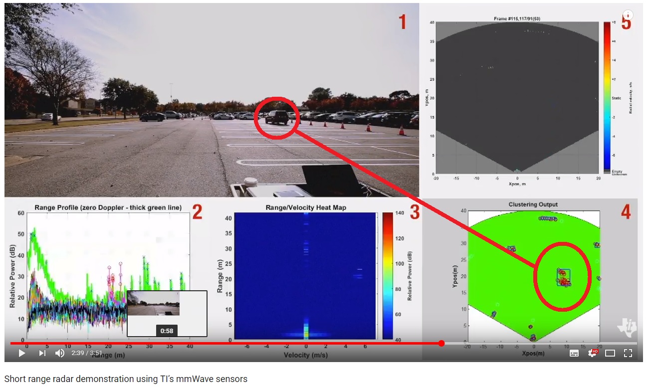
B.1 Why do those points distribute like this? And is it reasonable?

B.2 There is a rectangle used for describing this cluster. Is it suitable for describing target physical size(car)?

Thank you in advance.

Best Regards,

Kevin Chan

  • Hi,

    The USRR mode could be used in a parking environment where cars do not have high speed. The purpose of USRR mode is not to be used on freeway

    What is the project/application you are working on?

    thank you
    Cesar
  • Hi Cesar,

    Actually, I'm trying SRR/USRR for BSD(Blind Spot Detection) under any kind of scenario. Also I'm trying taking the advantage of points cloud of USRR to describe target physical size. So far, I have met some issues for this application.

    1. The maximum velocity of USRR is quite low. Do you have any suggestion for improving USRR Maximum velocity and this improvement could keep performance?

    2. I'm not sure what reasonable distribution of points cloud of USRR should be. I found the video(at 2:39) as previous post that shows points cloud distributed almost two parts(front and rear) in the rectangle cluster. So I think this "rectangle" could be used for describing target physical size. But this "rectangle" cluster cases me to ask what reasonable distribution of points cloud of USRR should be. Moreover, why do those points distribute like this as shown in video(at 2:39)?


    Thank you

    Kevin Chan
  • Hi Kevin,

    Max-velocity is inversely proportional to the chirp-repeat rate. However, if you were to reduce the chirp-repeat rate but chirp over the same bandwidth (i.e maintain the same range-resolution), you'd need a higher slope. A higher slope implies that for a target at a given range, the IF frequency is higher. Hence, to sample that tone, the sampling frequency has to be increased.Unfortunately, in the SRR demo, for the USRR chirp, we've set the sampling rate to the maximum possible (for AWR1642). Hence, to increase the maximum velocity, you'd have to compromise on one of the other parameters (max-range, range-resolution and max-velocity). You can also investigate different algorithm-based max-velocity enhancement techniques, which are higher-layer algorithms (like trackers). In the SRR demo, we've implemented a version that uses the chinese remainder theorem. You may be interested in that. 

    While I cannot comment on that particular video, in general, my belief is that it is due to the detection algorithms that we use (CFAR-CA). These algorithms  detect the start point and the end point of a distributed target (i.e a large target like a car), but do not detect points in-between. Other algorithms like CFAR-OS may be better at detected more points on a distributed target.

    Regards

    Anil