This thread has been locked.

If you have a related question, please click the "Ask a related question" button in the top right corner. The newly created question will be automatically linked to this question.

IWR1642BOOST: the problem with SPI connectivity

Part Number: IWR1642BOOST
Other Parts Discussed in Thread: DCA1000EVM,

Dear, experts

Thanks to you all, i've enjoyed the device and its applications.

Today i received Data Capture Card which is called DCA1000EVM,

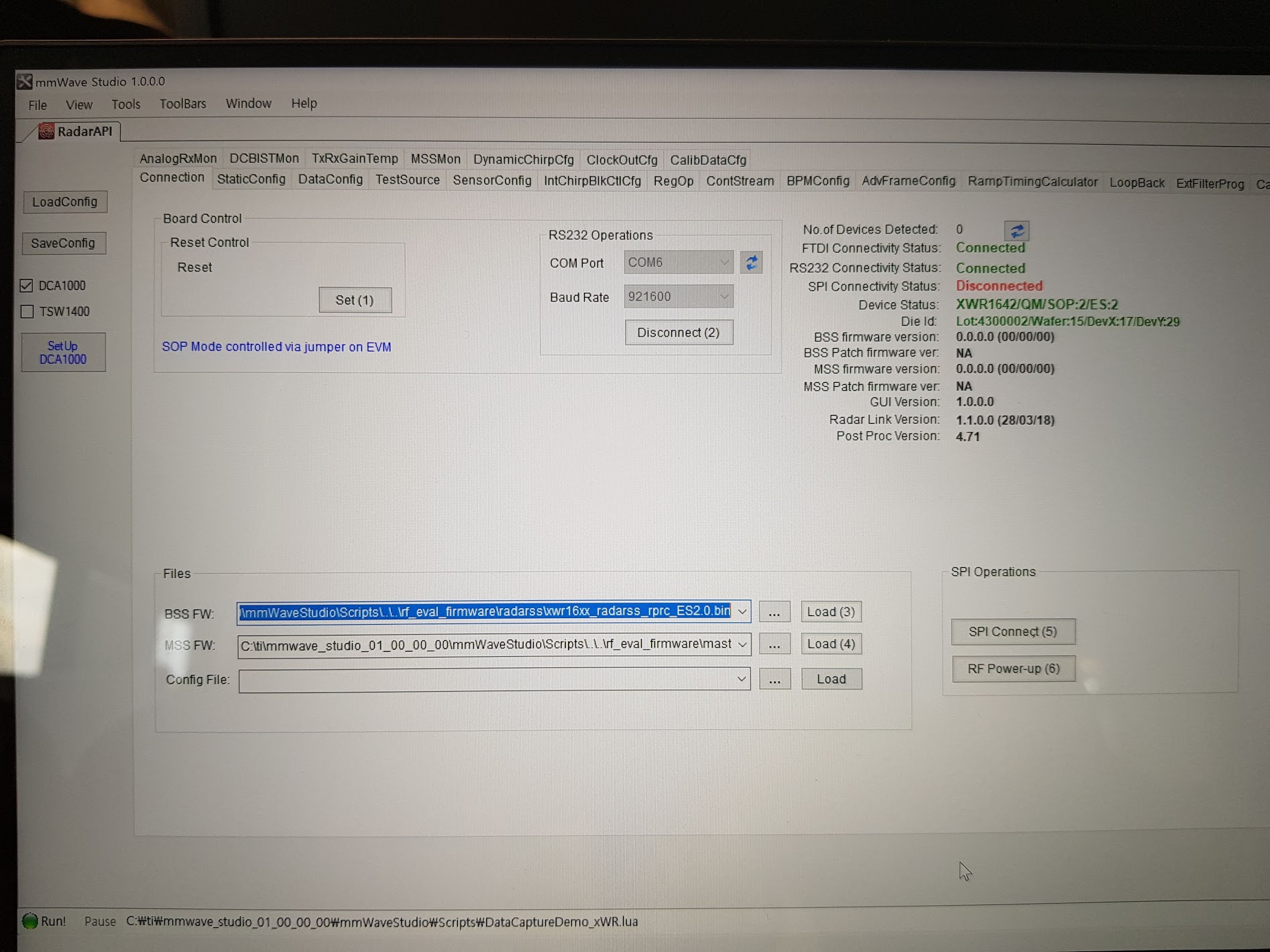
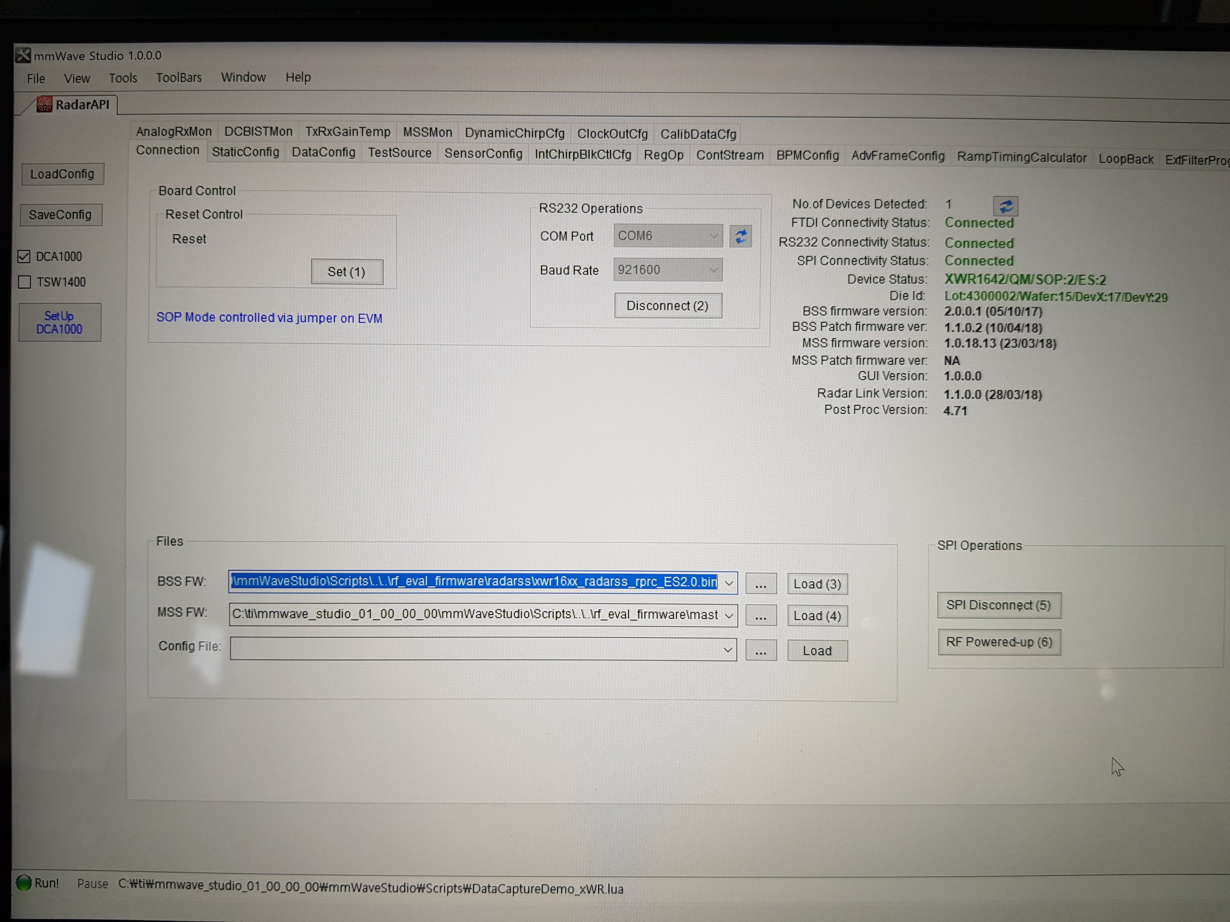
and faced a problem on SPI connectivity.

i removed the jumper on SOP2 and mounted the jumpers on SOP1, 0 perfectly.

also the Samtec cable is perfectly connected as well.

Thank you 

  • Jungsang,

    Can you provide more information so we can better understand the SPI connection issue you have posted here. At this point, there is very little information to go off to diagnose the issue.

    Please confirm the following physical setup:
    - 2 USB micro cables (one for IWR1642BOOST, one for DCA1000)
    - 2 power supplies (both 5V, 2.5A)
    - 1 ethernet cable

    Have you tried to click the "SPI Connect" button? What does the console window say when you click this button?

    Have you tried use the Capture Demo Script that comes with the mmWave Studio installation? Please refer to the DCA1000 Quick Start Guide here: www.ti.com/.../spruik7.pdf

    This guide details all of the steps, both hardware and software related, to get you started.

    Regards,
    Kyle
  • Hi Kyle,

    Thanks to you, i successfully connected SPI. Thank you very much.

    But the problem is i don't know how to do the next steps after it.

    For your info, i am not a developer but just a student who is interested in this device.

    (even my major is nothing related with computer programming lol)

    According to the user guide,  on pages 5,  a new program appears , which is called Radar Studio.

    I've tried to find it but i have no idea how to get this program.

    I'll really appreciate if you tell me how do get the program in detail.

    Also  is it okay to remove a jumper that is on SOP1  ?

    Applications that TI posted on ti Gallery are supposed to remove the jumper on SOP1 and SOP0 , and then test it.

    So i wonder if i can remove the jumper on SOP1 after mmWave studio since i want to do some tests , for instance, 'people count' and 'water level measurement '

    Thanks !

  • Jungsang,

    Radar Studio was the predecessor to mmWave Studio. When the User's Guide refers to Radar Studio, you can use that term interchangeably with mmWave Studio.

    You should try using the Capture Demo Script that is shown in your screen shots. That script implements a capture and basic analysis of 8 frames of data. You can also look at the LUA script source code to understand the steps taken in mmWave Studio to configure the device and trigger a frame.

    With regards to the SOP modes, please refer to section 2.7.1 in the User's Guide for IWR1642BOOST. You can find the user's guide here: www.ti.com/.../swru521b.pdf

    The labs and experiments posted on TI's Resource Explorer each have Developer's Guides that provides the instructions on both the hardware setup and software setup for running each one. Please refer to that documentation for more detailed information.

    Regards,
    Kyle
  • Hi Kyle,

    i think i found out why it didn't work.

    it was because FPGA version was not read on mmwave studio even though everything was connected fine

    i see you on another post

    thanks !