This thread has been locked.

If you have a related question, please click the "Ask a related question" button in the top right corner. The newly created question will be automatically linked to this question.

TDC1000-GASEVM: Oh My Goodness it doesn't work out of the box!

Part Number: TDC1000-GASEVM

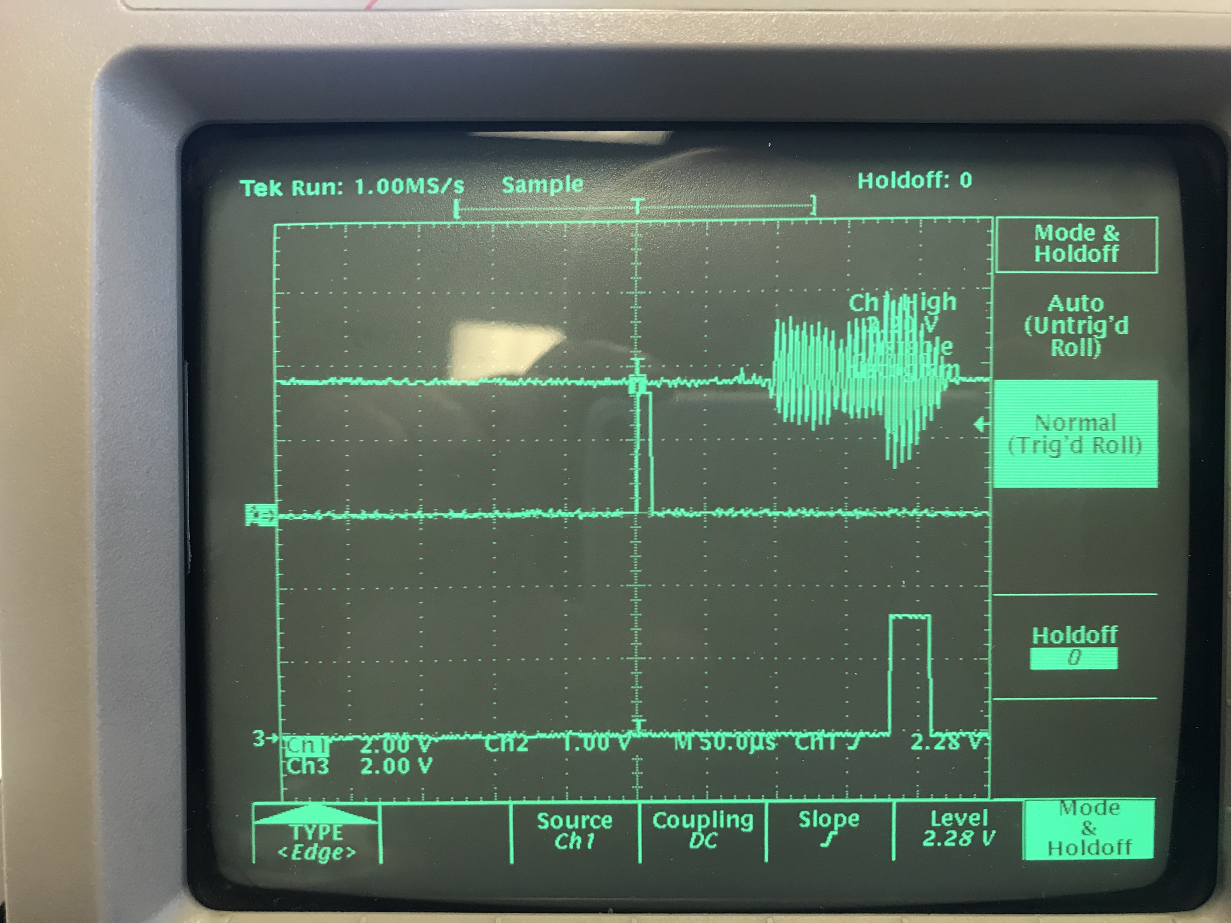
I spent hours trying to get this evaluation board to work with a 300kHz transducer in air to measure any small distance.  Now when I look at the transducer with the scope I see 300kHz 30V pulses and what looks like ringing but see no evidence of an echo even when the baseline is expanded greatly on the scope.  I may have a defective transducer so I am getting a few different kinds. What I mainly want to know now is related to the configuration registers.  Is there a Webench tool that can generate the configuration file for the application?  It is implied that there is but I can't find it anywhere. The configuration screen is pretty cryptic and I'm not quite sure if I should be in Mode 0,1,2 I am doing pulse echo single transducer.

Thanks

  • Michael,

    Please run the GUI as per the instruction in www.ti.com/.../sniu026a.pdf.

    Refer the datasheet : www.ti.com/.../tdc1000.pdf for the Mode description in Sections 8.4 Device Functional Modes.

    Mode 0 is typically used to measure short TOF and in Gas EVM you can typically use Mode 0 and use single transducer.
  • Bharat: Thanks for the mode 0 clarification. I see references to a Webench that generates a config file for this part. Does that exist?
  • TDC1000_Config0                         25
    TDC1000_Config1                         00
    TDC1000_Config2                         00
    TDC1000_Config3                         00
    TDC1000_Config4                         00
    TDC1000_TOF-1                           00
    TDC1000_TOF-0                           00
    TDC1000_Error_Flags                     00
    TDC1000_Timeout                         00
    TDC1000_Clock_Rate                      00
    TDC1000_Conts_Trigger                   00
    TDC7200_Config1                         00
    TDC7200_Config2                         00
    TDC7200_Interrupt_Status                00
    TDC7200_Interrupt_Mask                  00
    TDC7200_Coarse_Cntr_Ov_H                FF
    TDC7200_Coarse_Cntr_Ov_L                FF
    TDC7200_Clock_Cntr_Ov_H                 FF
    TDC7200_Clock_Cntr_Ov_L                 FF
    TDC7200_Clock_Cntr_Stop_Mask_H          00
    TDC7200_Clock_Cntr_Stop_Mask_L          00
    TRIGGER_UPDATE_FREQ                     0001
    TDC_AVG/STDEV_NUM_ELEMS                 000A
    SAVE_GRAPH_DATA_TO_FILE                 00
    FLOW_MODE_SELECT                        00
    Y-SCALE_CENTER                          0032
    X-SCALE_RANGE                           0032
    MEASURE_RTD1                            00
    SAVE_RESULT_REGR_TO_FILE                00
    GRAPH_MULTI_STOPS                       00
    TDC_SELECT                              00
    TEMP_RTD_SELECT                         00
    TEMP_RTD_MODE                           01
    TEMP_AVG/STDEV_NUM_ELEMS                000A
    SAVE_TEMP_DATA                          00
    GRAPH_YMAX_DATA                         00000000004C4B40
    GRAPH_YMIN_DATA                         0000000000030D40
    TDC1000-HV_DRV_EN1                      01
    TDC1000-HV_DRV_EN2                      01
    HV_DRV_EN1_Period                       001E
    HV_DRV_EN2_Period                       001E
    ENABLE_POWER_CYCLE                      00
    CLK_FREQ_(1-16MHz)                      1.200000
    CLK_SOURCE_SEL                          03
    CPU_CLK_FREQ                            04
    CPU_CLK_EN                              01
    TDC1000-HV_BST_PWR_EN                   01
    HV_BST_PWR_EN_Period                    0000
    FWD2REV_FLOW_DELAY                      0000
    TDC1000-IMPE_MATCH_EN                   00
    ENABLE_UART_STREAM                      00
    ENABLE_MSP430TIMER_TDC                  00
    TDC1000_Config0                         25
    TDC1000_Config1                         00
    TDC1000_Config2                         00
    TDC1000_Config3                         00
    TDC1000_Config4                         00
    TDC1000_TOF-1                           00
    TDC1000_TOF-0                           00
    TDC1000_Error_Flags                     00
    TDC1000_Timeout                         00
    TDC1000_Clock_Rate                      00
    TDC1000_Conts_Trigger                   00
    TDC7200_Config1                         00
    TDC7200_Config2                         00
    TDC7200_Interrupt_Status                00
    TDC7200_Interrupt_Mask                  00
    TDC7200_Coarse_Cntr_Ov_H                FF
    TDC7200_Coarse_Cntr_Ov_L                FF
    TDC7200_Clock_Cntr_Ov_H                 FF
    TDC7200_Clock_Cntr_Ov_L                 FF
    TDC7200_Clock_Cntr_Stop_Mask_H          00
    TDC7200_Clock_Cntr_Stop_Mask_L          00
    TRIGGER_UPDATE_FREQ                     0001
    TDC_AVG/STDEV_NUM_ELEMS                 000A
    SAVE_GRAPH_DATA_TO_FILE                 00
    FLOW_MODE_SELECT                        00
    Y-SCALE_CENTER                          0032
    X-SCALE_RANGE                           0032
    MEASURE_RTD1                            00
    SAVE_RESULT_REGR_TO_FILE                00
    GRAPH_MULTI_STOPS                       00
    TDC_SELECT                              00
    TEMP_RTD_SELECT                         00
    TEMP_RTD_MODE                           01
    TEMP_AVG/STDEV_NUM_ELEMS                000A
    SAVE_TEMP_DATA                          00
    GRAPH_YMAX_DATA                         00000000004C4B40
    GRAPH_YMIN_DATA                         0000000000030D40
    TDC1000-HV_DRV_EN1                      01
    TDC1000-HV_DRV_EN2                      01
    HV_DRV_EN1_Period                       001E
    HV_DRV_EN2_Period                       001E
    ENABLE_POWER_CYCLE                      00
    CLK_FREQ_(1-16MHz)                      1.200000
    CLK_SOURCE_SEL                          03
    CPU_CLK_FREQ                            04
    CPU_CLK_EN                              01
    TDC1000-HV_BST_PWR_EN                   01
    HV_BST_PWR_EN_Period                    0000
    FWD2REV_FLOW_DELAY                      0000
    TDC1000-IMPE_MATCH_EN                   00
    ENABLE_UART_STREAM                      00
    ENABLE_MSP430TIMER_TDC                  00
    Can I have you look at the config file attached? This is for a 300kHz transducer in air. Max distance about 12".

  • Bharat:

    Here's a scope photo of what I am getting with a 200kHz transducer. Keep in mind I've tried several transducers of different frequencies and get the same results. Top trace is comp, second trace is Start, and thrid trace is Stop.  I realize that Stop pulse is latching on to ringing but even if I blank that out using short ToF I still don't see a valid echo on comp. My range is only going to be roughly 1 foot. Suggestions please.

  • Mike,

    Please adjust your boost your COMP pin out data, the device could miss the COMP data since it is less than the VCOM value.