This thread has been locked.

If you have a related question, please click the "Ask a related question" button in the top right corner. The newly created question will be automatically linked to this question.

IWR1443: profile parameter guidelines

Part Number: IWR1443
Other Parts Discussed in Thread: MMWAVE-STUDIO

Hi,

I am looking for any guidelines for some of the parameters in the profileCfg cli command. I have reviewed postings and various ti pdf documents but I have a few questions.  Please make any suggestions or comments you desire.

1. idleTime: I have seen this parameter vary from 7 to 429 usec.  I see no reason to have it extend much beyond 7 usec.  What should a person consider here?  I assume any ringing from the end of the ramp back down has quiescent  in 7 usec.

2. adcStartTime: From a number of published config files, it appears that a value of 7 usec appears to be very standard.

3. rampEndTime: This time plus the idleTime should equal the chirp cycle time which specified by the framePeriodicity parameter in the frameCfg cli command.

4. txStartTime: From a number of published config files, it appears that a value of 1 usec appears to be very standard.

5. Should there be much time, if any, from the end of the ADC sampling interval to the end of the ramp?

6. adcSamplingTIme: Equals numAdcSamples/digOutSampleRate (msec); the adcStartTime + adcSamplingTIme< rampEndTime

7. freqSlopeConst: freqSlopeConst*adcSamplingTIme<4GHz

8. rxGain: I have observed values around 30.  The sdk user manual refers to the mmwavelink doxgen for details but I can not find any there.  Please comment.

9.  The maximum range (not considering any windowing effects) is given by: c*digOutSampleRate/2/freqSlopeConst.  Are there any other considerations for choosing the parameters in the ratio of digOutSampleRate/freqSlopeConst to yield a particular maximum range other than to insure the above constraints are met?  What are reasonable or practical ranges for digOutSampleRate and freqSlopeConst?

Thanks.

Al

  • Hi Allen,

    Most of these questions can be answered by the following app note and the videos provided in mmWave Training Series.

    App note: Programming Chirp programming in TI Radar Devices.

    mmWave Training Series: https://training.ti.com/mmwave-training-series

    1. idleTime: The minimum idle time requirements are defined in section 5.1 of the above app note. You may want to select larger idle time depending upon frame duty cycle requirements. You can also increase velocity resolution (at the expense of max velocity) by increasing the idle time. If you want to keep both max velocity and higher velocity resolution, you will need to increase the number of chiros and also have less idle time.

    2. ADC Start Time: Please refer to the following thread:

    Question on adcStartTime  and the thread referenced by it:

    AWR1642BOOST: Understanding changes in "TX start time" and "ADC valid start time" 

    3. Ramp End time: The first part is correct i.e. Chirp Cycle Time = Ramp End time + Idle time (Refer to the image shown in https://dev.ti.com/mmWaveSensingEstimator). However, FramePeriodicity in frameCfg is used to specify the total frame time.  FramePeriodicity / (Num chirps x chirp cycle time) defines the frame duty cycle. For the OOB demo, it should be atleast 50%. Refer to the mmWave SDK user guide.

    4. txStartTime: Refer to the thread in item 1 above.

    5. Excess Ramp Time: Refer section 5.3 of App note: Programming Chirp Parameters in TI Radar Devices: . The concept of excess ramping time is defined here.

    6. adcSamplingTIme: That is correct. Refer section 5.3 of the above app note.

    7. freqSlopConstant: The correct equation should be: Frequency Slope x Ramp End Time < 4GHz (note ADC start time and Excess ramp times are part of ramp end time and as such they count towards the RF bandwidth).

    8. Rx Gain: It is defined in mmWaveLink Doxygen documentation available in the mmWave SDK at SDK_INSTALL_DIR>/packages/ti/control/mmwavelink/docs/doxygen/html/index.html

    Click on the Sensor link under Modules, then rlSetProfileConfig. Direct link for rlProfileCfg_t Struct Reference is provided below.

    <SDK_INSTALL_DIR>/packages/ti/control/mmwavelink/docs/doxygen/html/structrl_profile_cfg__t.html

    9. Please refer to the app note provided above and mmWave Link Doxygen documentation. In addition mmWaveSensingEstimator generates the correct values for these parameters for you based on the provided application parameters.

    Please mark this thread resolved if your query is answered otherwise get back if more support is needed.

    Thanks

    -Nitin

  • Hi Nitin,

    Thank you for the very helpful information.  

    It did bring up one question regarding the sign the txStartTime.   It was stated in this thread that

       If the tx start time is positive, the tx start is delayed w.r.t the knee of the ramp.

       If the tx start time is negative, the tx starts before the knee of the ramp.

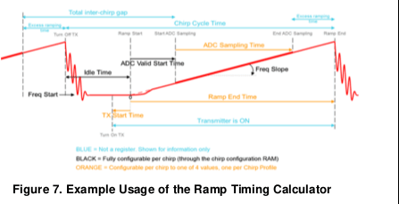
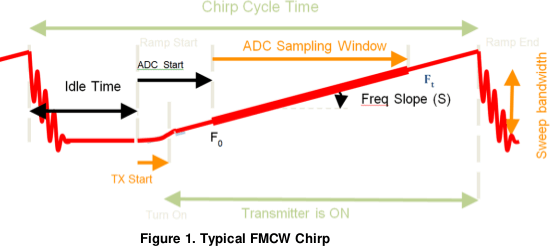
    I would like to believe that the transmitter should be turned on before the ramp starts which would make the sign to be negative but the sign of this parameter is always positive for the config files in the example chirp folder of the mmwave_industrial_toolbox_2_5_2 and also in the default configuration in the demo visualizer gui.  I also noted that in programming_chip_parameters.pdf, Figures 1 and 7 have this parameter graphically defined differently.  Can you please clarify this?

    I also noticed that the idleTime in the demo visualizer gui is very large (429 us) which is not characteristic with all the other configuration examples.   Can you please provide any thoughts on why this parameter is to large when it may not have to be?

  • Hi Allen,

    • TX Start time: If the value of TX Start time is negative, the transmitter will be turned ON before the start of the ramp and the OOB demo does allow you to set negative value for it even though the various demo configuration files do not have a negative value for this parameter. Typically, you may need to play with this parameter only during advanced performance testing of your system. Refer to section 5.4 of the App note I pointed to above and you can see that MMWAVE Studio Ramp Timing Calculator utility shows different values of ADC start time corresponding to different synthesizer settling times such as 90%, 95%, 99% etc. Regarding your point about the TX start times shown in Figures 1 and 7, they just show both positive and negative TX start times: Figure 7 shows a negative TX start time while Figure 1 shows a positive TX start time.

    • Idle Time:As mentioned in my previous response, the value of idle time is dependent upon the scene requirements such as max velocity and velocity resolution but also other system requirements such as the time required to send data over CSI or LVDS. From section 5.4 of the App note referred above:
      • For example, if the raw ADC data is being set over the CSI or LVDS path, the idle time setting needs to make sure the transfer on the CSI/LVDS interface is complete before the next chirp data is available. The time available for this data transfer is = “ramp end time” + “idle time”. In case of CSI, the overhead time due to the MIPI protocol also needs to be accounted for.

    • The MMWAVE-STUDIO or Sensing Estimator only calculates the minimum Idle time based on the chirp design but as part of overall system design, you need to take care of the other system parameters such as data transfer times etc.

    Thanks

    -Nitin