This thread has been locked.

If you have a related question, please click the "Ask a related question" button in the top right corner. The newly created question will be automatically linked to this question.

AWR1243: AWR1243P:Unknown noise

Part Number: AWR1243

Hello,

I'm using AWR1243P+TDA3.

I got AD data and processed FFT with matlab.

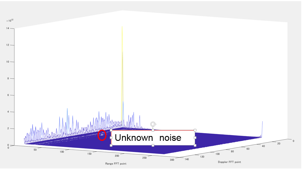
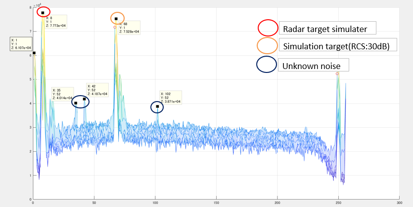
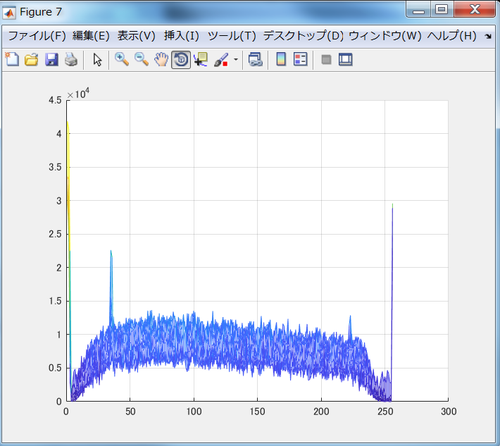
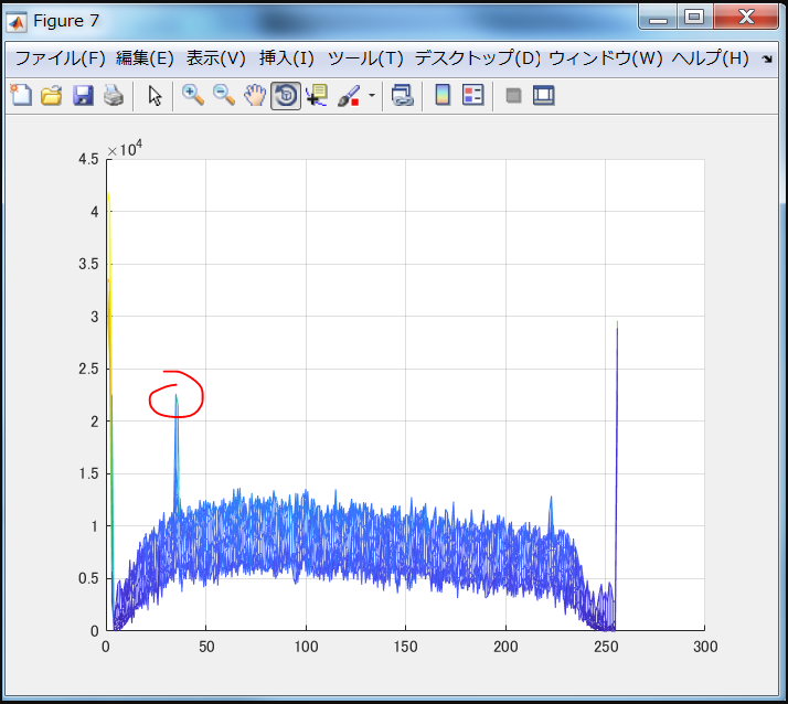
As a result ,unexplained noise occurred.

This noise has Doppler(Doppler peak:52) components in situations with only stationary objects. Furthermore, this noise is generated at a position shifted from the largest peak by about 34 points in the distance FFT direction.
What is the cause of this noise?

* Although this noise is quite small in MATLAB processing, it becomes large when processing with EVE of TDA 3, which has a big influence on target detection.

  • Can you please provide more information about your testing environment and your chirp configuration? At this point, there is very little information to go off and attempt to offer a solution.

    Regards,
    Kyle
  • Thank you for your reply.


    About measurement environment
    On the desk, set the target at a distance of 30 cm.
    * Although it is not an image measurement environment, similar results are obtained when measured with a radar target simulator in a shield room.

    · Radar settings
    Profile Config
    start freq: 79.81 GHz
    freqSlopeConst: 0.0366GHz / uS
    ramp end time: 20us
    idleTimeConst: 10us
    adcStartTimeConst: 6us
    numAdcSamples: 256
    digOutSampleRate: 18.75MHz
    hpfCornerFreq 1: 700 kHz
    hpfCornerFreq 2: 2.8 MHz
    rx Gain: 48

    Generate 128 chirps with the above setting, and use BPM MIMO function in M series.

    Regards,
    Takahashi.

  • Hi Takahashi,

    Can you also please describe the hardware platform being tested? Is this a TI Boosterpack or a custom PCB with AWR1243P installed?

    Thank you,
    -Randy
  • Hello,Randy
    Thank you for reply.

    I used custom board.(The board is created with reference to TI's AWR1243 reference.)

    thanks and regards,
    Takahashi.
  • Hi Takahashi,

    Some more follow-up questions:

    • Can you please attach the matlab dataset you are working on?
    • What is the test target in this situation?
    • Does this spur change depending on target? Does the spur track with target distance?
    • Can you please clarify what you meant by "Although this noise is quite small in MATLAB processing, it becomes large when processing with EVE of TDA3, which has a big influence on target detection."?
    • Can you please specify your method of determining that this noise is "a big influence".
      • A 20dB SNR is a reasonable target.
      • Can you please specify what the noise floor, spur power and signal power are on your board?
    • Can you compare this to the AWR1243 boosterpack performance seen in the same target environment?

    Thank you,

    -Randy

  • Measurement result in shield room

    M codes

    mat.zip 

  • Hello Randy,


    I list the answer to your question.

    >Can you please attach the matlab dataset you are working on?
     Please refer to the attached source file.

    >What is the test target in this situation?
     In this case, the radar target simulator is the target. The place is a shield room.

    >Does this spur change depending on target? Does the spur track with target distance?
     If there is a strong RCS target, it will occur at the corresponding position.

    >Can you please clarify what you meant by "Although this noise is quite small in MATLAB processing, it becomes large when processing with EVE of TDA3, which has a big influence on target detection."?
     Attach the image after TDA processing. Since the noise peak in this image is almost the same power as the target such as people, it is a problem.
     *Previously uploaded images were merely calculated absolute values of FFT, but this time we have converted (Using "mmwavelib_log2abs.c",void mmwavelib_log2Abs16()) and data of Rx 4ch and Tx 3ch (total of 12 channels) were added up.

    >Can you please specify your method of determining that this noise is "a big influence".
     We want to detect the iron mass, people and road surface with radar. In that case, the RCS difference may occur between 20 and 30 dB. Therefore, generation of this noise is regarded as a problem.
     * In particular, we think that this noise has a power equivalent to that of the low RCS, so it is a big problem.

    >Can you compare this to the AWR1243 boosterpack performance seen in the same target environment?

     We do not have a booster pack, so we can not do this verification.
  • Hi Takahashi,

    Thank you for sending over that data. I will review and get back with you. Again, some follow-up questions/comments:

    • Please confirm distances of the targets again
      • 30 cm is what you mentioned initially
      • If the TX output power is high and the target is high RCS you may be seeing TX to RX antanna coupling from very close targets -- this is a known radar systems issue typically observed in bumper mounted configurations and other large RCS, close range surfaces.
      • Based on your comment that the spur appears to track large RCS objects, this sounds like what your system is experiencing 

    • Could you compare these short-range results to longer-range target or noise floor measurements?
    • What ADC sampling mode and frequency is being used? Could you send over the complete AWR settings?
      • Using the full complex IQ ADC sampling provides better noise figure which may improve SNR in your scenario
    • What type of radar target simulator is being used? 
      • Are these just static reflectors or something else?
    • What kind of noise floor and spurs does your sensor see in the radar testing shield room with no target present?
      • We need to get a better understanding of what the noise floor of your sensor looks like

    Thank you,

    -Randy

  • Hello Randy,

    I list the answer to your question.

    >Please confirm distances of the targets again
    I definitely mentioned the target of 30 cm in the first content.
    Regarding the image uploaded the other day, I wanted to show that this noise is occurring under certain conditions (Doppler is 51st, Range is 34 points shifted) when the RCS is strong.

    >Could you compare these short-range results to longer-range target or noise floor measurements?
    We do not consider verification at long distances. This is because it is known that this noise does not occur because the received radio wave is weak in the case of a long distance.

    >What ADC sampling mode and frequency is being used? Could you send over the complete AWR settings?
    Please check the files in the ZIP folder.

    >What type of radar target simulator is being used? 
    At first we had set up a small corner reflex.
    In the previous verification, we installed a device that delays the radio waves with arbitrary values.
    * This equipment is installed 2 meters away from the radar, the simulated target is set at 20 m, and the range is set to not use it.

    >What kind of noise floor and spurs does your sensor see in the radar testing shield room with no target present?
    Upload measurement result of shielded room without target.

    thanks and regards,

    Takahashi

    Result of no target in the Shield room.(Processed EVE) 

    AWR setting

    5102.AWR1243P setting value.zip

  • Hi Takahashi,

    Any change in the status of this issue on your side?

    Just to confirm, does this spur in the no target noise floor image correspond to the unknown noise source you are tracking? Can you attach this no target dataset as well?

    If this is the noise you are tracking, then with no target, the only sources left are sources on the PCB itself.

    • Have you measured TX/RX antenna coupling on your board?
    • Have you checked to see if the spur level can be modulated with TX output power, RX gain, or number of TX/RX active/disabled or specific TX/RX channel combinations being active/disabled?
    • Can the spur level be modulated with different start frequencies?
    • Different ADC start times? 
    • Different idle times?
    • Different ADC sampling rates?

    Thank you,

    -Randy

  • Hello Randy,

    I list the answer to your question.

    First, we will send you the AD data measured in the shielded room without the target.

    Confirm with each person in charge about PCB check and other pointed out contents.

    Thanks and regards,

    Takahashi

    ad-20181109-121141.zip

  • Hi Takahashi,

    Please let me know as soon as you have answers to my additional questions.

    Thank you,
    -Randy
  • Hi Takahashi,

    I haven't seen a reply on this issue in the last week. Can you please verify that this is still an open issue and reply to my last questions?

    Since you verified that you are seeing spurs even in the no-target, isolated scene, I think this focuses the debug onto your PCB implementation. Can you please provide answers to that last list of questions?

    Thank you,
    -Randy
  • Hello Randy,

    I list the answer to your question.

    >Have you measured TX/RX antenna coupling on your board?
     We have no equipment and can not be confirmed.
     
    >Have you checked to see if the spur level can be modulated with TX output power, RX gain, or number of TX/RX active/disabled or specific TX/RX channel combinations being active/disabled?
    When Tx / Rx is enabled or disabled, the overall field power fluctuates, and the power of the spur fluctuated accordingly. However, the spur never disappeared.

    >Can the spur level be modulated with different start frequencies?
    When it changed to 76 GHz, the power of spurious decreased, but it did not disappear.

    >Different ADC start times?
    I changed the setting to 100 and 1000, but it did not change.

    >Different idle times?
    I changed the setting to 500 and 1500, but it did not change.

    >Different ADC sampling rates?
    I changed the setting to 20000 and 15000, but it did not change.

    Thanks and regards,
    Takahashi
  • Takahashi,

    Thank you for that feedback.

    If the spur power was proportional to TX output power or number of TX, this means we are probably dealing with something coupling noise into the XTAL->VCO->PA path.

    Would it be possible for you to list the IF frequencies of the spurs seen with different start frequencies?

    With spur issues like this we are searching for power noise, digital processing noise that has coupled into the RF. Searching through the spur list and cross-referencing those frequencies, and harmonics with known noise sources may help identify the source path.

    Can you please run the system with a zero-slope chirp? Can you run with radar absorber directly above the antenna? I would like to try and minimize all RX return noise and look at just the internal VCO noise.


    Thank you,
    -Randy