This thread has been locked.

If you have a related question, please click the "Ask a related question" button in the top right corner. The newly created question will be automatically linked to this question.

CCS/IWR1642BOOST: Fail to GPIO Configuration In IWR1642

Part Number: IWR1642BOOST

Tool/software: Code Composer Studio

Hello TI,

in my application i need to set GPIO when motion is detected 

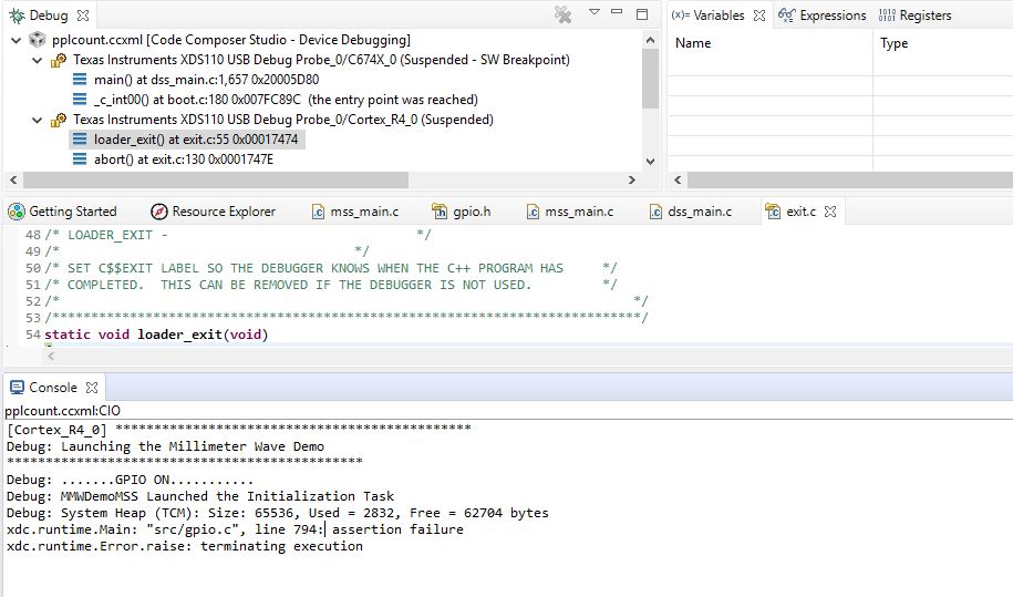
but i try to Config GPIO, It's not accept GPIO Configuration shows the asserts problem 

for GPIO configuration i take reference from  CCS Cloud lab0005-high-accuracy-16xx and try to make changes ti provided  lab0005-high-accuracy-16xx project 

please try give step for how configure GPIO and documentation 

i attach image file for reference

Thanks TI  

  • Hi Rahul,

    All of the mmWave SDK driver documentation (including GPIO) is found in the mmWave SDK docs directory in C:\ti\mmwave_sdk_<ver>\docs\mmwave_sdk_module_documentation.html.

    You can also look at the following post as an example.
    e2e.ti.com/.../2706379

    Regards,
    John
  • Hi,

    I configure GPIO Successfully in High accuracy  demo code but same procedure use to Configur GPIO in PPLCount Demo code it's shows assertion failure  problem

    provide some GPIO configuration step or some Documents for PPLCount Demo code

    there is some changes related to GPIO Config and use in Hgh accuracy code in between CCS imported and CCS Cloud MSS Source code...?

    Can you  provide CCS Cloud Source code it's help me lot further development

    Thank you for your  valuable response Jhon

    Regards,

    Rahul

    Debug Console Output

  • Rahul,

    CCS Cloud version is not currently supported for TI mmWave devices and will likely cause problems.  Please follow the instruction in the setup guide in the mmWave SDK Demo - 16xx lab on the TI Resource Explorer to create a working CCS project for the mmWave SDK demo from the Industrial Toolbox.

    Regards,

    John

  • Hello Jhon,

    Thank you for support and your valuable guidelines,

    GPIO2 Configure Successfully and use for DS3 LED ON/OFF when sensor Start/Stop

    Issue is.....,
    1. It's GUI is not work when i try to debug the same code but when flash same code bin file on IWR1642Boost EVM Board for Output, GUI work Fine ( High accuracy demo visualizer detect object and Sensor start/stop LED Set Successfully)
    2.GUI(Comport is not connected) is not work when i try to debug the same code and when flash same code bin file on IWR1642Boost EVM Board for Output, GUI (Com Port Connected ) but not showing PPLCount

    please help me or guide me to resolve this issues ASAP

    Thanks and Regards,
    Rahul
  • Hello Rahul,

    Since the original issue of this thread is resolved, please create a new thread for other questions/issues.

    Thanks,
    John