This thread has been locked.

If you have a related question, please click the "Ask a related question" button in the top right corner. The newly created question will be automatically linked to this question.

DRV411: DRV411 H-Bridge driver and compensation issue

Part Number: DRV411

Dear TI engineer,

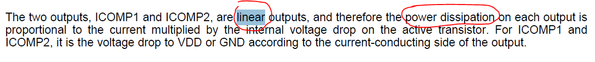
when I study the datasheet of DRV411, it mentioned that the H-Bridge is driven by linear signal. And the power consumption is voltage drop multiply the current through.

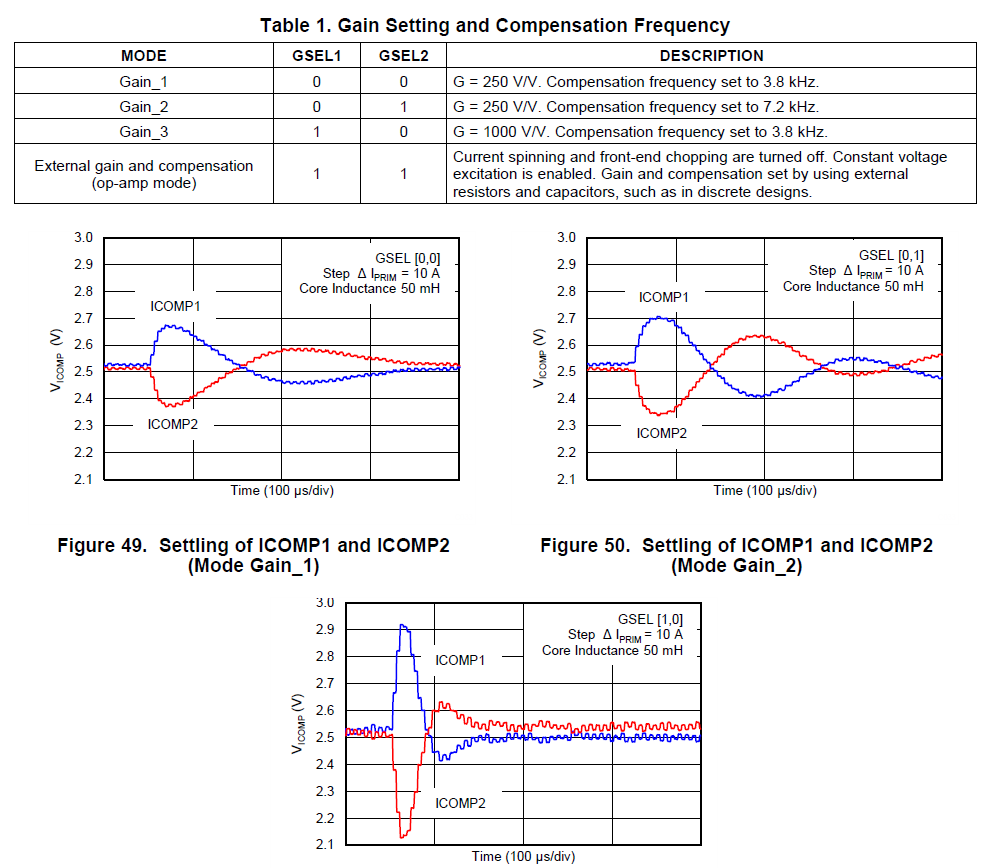
But, in the section describes the Gain Setting and Compensation, the picture shows that the curve of Vcomp is not smooth which is not like linear driven. Detailed like below.

So, could you help to tell me why the curve is not smooth and what the Compensation Frequency means?

  • Hello  user3912090,

    The DRV411 samples the hall sensor at about 1Mhz as it does its spinning current method.  This will translate to a sampling of around every 250KHz.  This is where you see the non smooth lines at the IComp voltage.  This is the part sampling rate and changing of the IComp.  

    The compensation frequency is the frequency of the pole of the loop filter.  The best way to explain this in by the DRV421 application note which uses similar output.  Your inductance is expected to be lower for placing a hall sensor in the airgap.