This thread has been locked.

If you have a related question, please click the "Ask a related question" button in the top right corner. The newly created question will be automatically linked to this question.

DRV421: Dose the G_mod has any physical meaning? And how to comprehend the two signal paths from Ip to Is

Part Number: DRV421

Dear TI engineer,

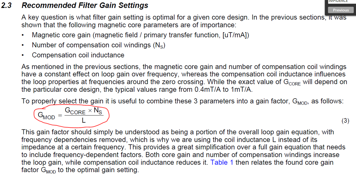
When I study the DRV421's document SLOA224, I found a parameter Gmod=Gcore*Ns/L in section 2.3 like below. Actually, I can't understand why we use this Gmod and what is it mean.

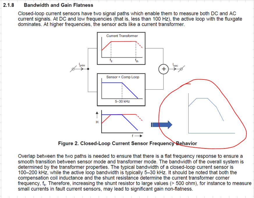
Another question is, when I study the section 2.1.8 Bandwidth and Gain Flatnees in document SLOA223. It says there are two signal path from Ip to Is. My understanding is that, the total gain equal to the summation of both path, because both path are working over all frequency range. But if this is correct, the gain curve could not be flat while flat Gain is our aim. 

There are many questions, it will be appreciative if you can explain previous questions.

Many thanks.

  • Ocean Lee,

    Thank you for using the forum to get your questions answered.

    First I will start off with Gmod.  This a Gain that is used in the feedback and is dependent on the gain seen at the core Gcore.  Gcore is the flux seen at the DRV421 for the amount of current sent through the primary.  That is why the units are in mT/A.  This value will depend on the core properties and the mechanical placement of the DRV421 relative to the air gap.  In Table 1 of SLOA224 you will see we made an assumption in the Gcore of 0.6mT/A and 1000 windings.

    The two signal paths are basically attempting to balance the field seen at the DRV421, field equal to zero at DRV421.  At lower frequency the sensor and compensation loop are doing this.  At higher frequency we have a transformer effect that is forcing the current through the compensation coil.  During the overlap both components are active and they are both doing the same effect.  They combine to due the same thing so one effect will compensate more or less just to get the same results, which is no field seen at the DRV421.  The issues will come if your flat gain as you transition from low (Sensor +Comp loop) to high frequency(current transformer).

    You can get a rough idea or the overlap using the DRV421 System parameter Calculator.

    DRV421 System Parameter Calculator