Other Parts Discussed in Thread: TIDA-00151, , PGA450-Q1
Hi there,
I am working with the PGA450Q1EVM REV-C (including TI GER-A board and Murata transducer). I got familiar with the GUI and I am able to get range profiles from it. In order to test live feedback and set up a driver for the board, I am now trying to interface with the EVM using UART (RS232). However, I do not get any answer back from the PGA450 when sending command 0 (or any command for that matter).
I am following instructions from PGA450Q1EVM-S User's Guide and TIDA-00151 UART Demo Instructional (Rev. B).
Here are the steps I follow:
0) Connections:
a) Connect EVM board to 12V power supply
b) Connect USB cable from laptop to TI GER-A board (the TI GER board is connected to the EVM from the communication PCB)
c) Connect UART-to-USB cable from laptop to RS232 port on the EVM board
1) Program DEVRAM to use UART demo firmware
I follow the steps from section 2.2.1 (step 1 to 10) with Q1_TIDA-00151_Rev2_7_DEVRAM-UART.hex from TIDA-00151 UART & LIN Demo Firmware for PGA450-Q1 v2.4 (Rev. D) (note that the link says v2.4 but the .hex inside is rev 2.7)
The output reads DEVRAM Verification Successful
I do not disconnect power or any other cables. However I switch back micro controller to ACTIVE in the ESFR tab (is this step missing from the guide?).
At this point I assume that the PGA450 will respond to UART commands.
2) Sending/Receiving commands through UART
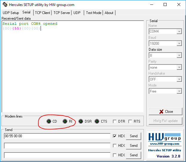
a) Using Hercules Setup Utility, I send command 0 (0x00, 0x55, 0x00, 0x00) as in the related question post. My EEPROM 0x1F address reads 00 so since my sensor address is 0 I send (0x00, 0x55, 0x00, 0x00) as opposed to (0x00, 0x55, 0x01, 0x00)
b) There is no output back from the EVM board... I tried with other sensor addresses as well. I also notice that the modem lines CD and RI are not green as in the posts from the related question.
3) Check UART communication through GUI
a) I also tried checking UART through the GUI but I am confused about step 4 (p.7) since I have the EVM and not EVM-S. Instead I assume connections are already done and do not touch the hardware.
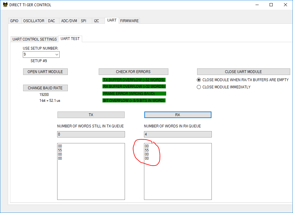
b) Other steps go well but when I type in the command, hit Tx and then Rx, the Rx queue reads exactly the Tx sent...
Any feedback or ideas on how to solve 2 and 3?
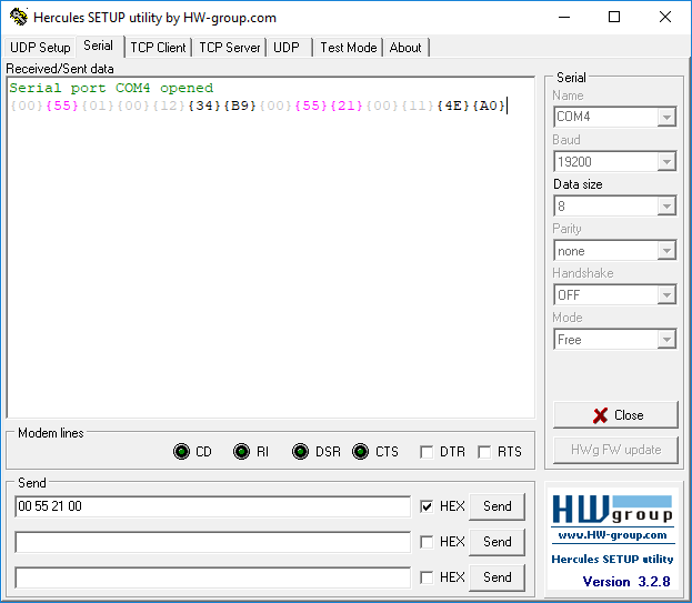
PS: I checked the cable by shorting Txd and Rxd and confirmed that I read back what was sent (using Hercules Setup Utility) as expected.