This thread has been locked.

If you have a related question, please click the "Ask a related question" button in the top right corner. The newly created question will be automatically linked to this question.

PGA900: PGA900: bi-wire 4-20mA current mode issue

Part Number: PGA900

I have some questions about the bi-wire 4-20mA output regarded to some test I did recently.

My PGA900 circuit was connected to W-bridge which is connected by 4 strain gauges, each is 350 ohm.

When I set 2.5 bridge voltage, then I found the current from pin FBP is almost 9mA at DAC_REG set by 0x0000(HEX).

So, my questions are as below, plz answer each question, very thanks.

1. Is that means the bi-wire current output will have a lower limit at 9mA???

2. As I know, the PGA900 isn't designed for such low resistance of strain gauge. So If I still want to use 350 ohm strain gauge, this issue will always there, right???

3. I had tried to use 1k ohm strain gauge, but the current is 4.5mA. So I reduced bridge voltage from 2.5V to 2.0V, then the current is lower than 4mA. But to reduce bridge voltage is not good idea, because the amplify rate also need to be increased, which means the noise will increase. Do you have any solution to limit current lower than 4mA on using 350 ohm strain gauge and 2.5V bridge voltage????

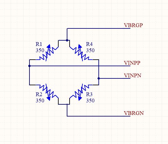
My W-birdge connection as below......

  • Hi Yimin,

    This is just Ohm's Law. The only way to reduce the current given a fixed voltage is to increase the impedance of the bridge.

    Regards,
  • DEAR Sir:

    You are right. But the resistance of W-bridge for load cell application always between 350 ohm and 1000 ohm be used, and the 350 ohm is very popular in load cell market. Most important is that it is hard to get the more than 1000 ohm strain gage to make the load cell, even you can purchases high resistance strain gage, you can’t accept the price. I really thank the PAG900 is a good product to make load cell circuit more compact and small. Of course, the PGA900 still have another output spec. (ex: UART, voltage, GPIO), but our customer need high response output and reliable signal. So current output is best choice. So, I really hope another solution can be provided from TI.


    Many thanks


    Frank

  • Hello Scott,

    Regarding to the output current issue of the PGA900, please find the below questions.

    1. The output current is equal to input bridge current + device's power comsumption current + DAC Setting value, is this right?

    For example with 350Ohm load cell and DAC is set 0x0000(HEX), the output current of the PGA is 2.5V/350OHm + 2.5mA + 0mA = 9.5mA

    The 9.5mA is an initial value that is great than 4mA,min. This is a issue for output current communication.

    Customer uses the popular load cell with 350 Ohm since it coming with lower price. so that customer prefer to use it.

    2. Why the input bridge current and device's power comsumption current are also taken into account for the output current?

    Customer think the brige current and device's power comsumption is NOT easy to be controlled since temperature change behavior.

    Brian

  • Hi Brian,

    1. Yes, that is correct.

    2. In a 4-20mA current loop output device, the only connections to the device are the power and the current return line. With only those two lines, the device's current consumption must be included in the output current. With that setup it is physically impossible not to include the device's current consumption.

    The bridge current and device's current consumption are not controlled, but do remain relatively stable during operation. Only the DAC output is used to control the total current output. The DAC Gain section of the datasheet describes the specifications for the DAC output buffer which affects this. Typically the DAC output is calibrated across temperature to improve the stability of the output current.

    The bridge sensor supply current limit is specified in the datasheet as 1.5mA for exactly the reasons you have mentioned. If it is allowed to consume more current, it pushes the output current above 4mA.

    If the customer is intent on using a 350ohm bridge, they have 2 options. They can either accept a smaller output range, or they can use an external buffer with its own power supply (it can be the same supply used for the Vpwr to the PGA900). The  buffer will take the VBRG output from the PGA900 as its input, and its output will go to the load cell.

    Regards,