This thread has been locked.

If you have a related question, please click the "Ask a related question" button in the top right corner. The newly created question will be automatically linked to this question.

AWR1642BOOST: How to Connect EVM Booster pack J6 pin5(AR_RS232TX) and pin7(AR_RS232RX) to PC/other host

Part Number: AWR1642BOOST

hi TI community,

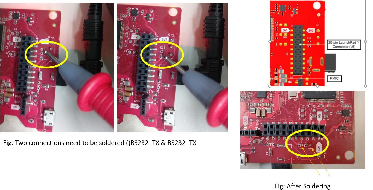
I want to know how can I connect the EVM Boosterpack J6 pin 5 and pin 7 UART Tx and Rx to PC instead of controlling the board from OOB USB UART cable which is integrated in USB type B connector on J8.

And what changes I need to make in main code to send commands and receive data on these pins instead of default pins mentioned in the code. 

thank you

  • Hello Shabirahmed,
    On the AWR1642BOOST EVM the UART TX and RX lines are accessible over USB interface using the XDS110 IC. This shows up as a COM port ( XDS110 Application UART) on the PC and any application on your PC can access it.

    Regards,
    Vivek
  • Hello Vivek,

    Thank you for your response.

    Actually, I do not want to access EVM via onboard USB interface(I already did that),  I want to access the EVM through J6 pin 5 & 7 UART. How can I connect it to PC/ other MCU?

    My main aim is to control the EVM from an FPGA board to send commands and receive data.

  • Hello Shabirahmed,
    You can disconnect the UART lines going to the onboard "TM4C1294NCPDTT3" chipset by removing the resisters R128 and R129 and connect the resisters that connect the signals to the J6 connector (R169 and R166). You can find the resister details in the schematic and the assembly pdfs at the following link :www.ti.com/.../sprr251

    Regards,
    Vivek
  • Hello Vivek,

    Thank you for your response.

    I managed to make the changes as said by you. Now i can sense signals on these two pins J6_PIN5 and PIN7. I used an UART to USB bridge to connect to PC. I could recieve some data over this J6 UART.

    I was not able to send the CLI commands over this new UART connection. Do I need to make changes of Pins in the source code so that the DEMO project can recieve the commands over this new line instead of the onboard XDS110 application/user UART[COM 'X'].

    After doing the connection I connected the USB cable J8 and also the new UART. I got 3 com ports on my PC.

    1. XDS110 application/user UART

    2. XDS110 auxiliary DATA port UART

    3. silicon LABS USB t UART bridge.

    I sent the CLI commands using the GUI and observed the data on the new port. I could receive some data but it were gibberish as shown in below picture. Can you help me in pointing me in right direction where I need to make changes so that I can send the CLI commands via J6 PIN5 & 7 and control the EVM. Thank you.

  • Hello Shabir ,
    Once to connect the R169 and R166 as you have shown above to also need to disconnect these lines from the onboard XDS110 by removing the R128 and R129.
    In the visualizer you should select the CFG port to the COM port number corresponding to the silicon labs UART USB bridge and the DATA port number to the XDS110 auxiliary DATA port UART. This is the port used to send data out. Make sure you select the right BAUD rates, 115200 for CFG port and 921600 for data port.


    Regards,
    Vivek
  • hello Vivek,

    I removed the R128 and R129 from the board and connected the EVM to PC over J6 UART pins.

    When I am trying to flash the EVM with Bin file over silicon labs UART PORT it gives following Error:

    [11/26/2018, 1:44:34 PM] [INFO] Cortex_R4_0: Flashing instance clean-up initiated...

    [11/26/2018, 1:44:34 PM] [INFO] Cortex_R4_0: Instance deinitialized!

    [11/26/2018, 1:44:53 PM] [INFO] Cortex_R4_0: Initialization complete.

    [11/26/2018, 1:44:53 PM] [INFO] Cortex_R4_0: Flashing process starting...

    [11/26/2018, 1:44:53 PM] [INFO] Cortex_R4_0: Connecting to COM Port COM5...

    [11/26/2018, 1:44:53 PM] [INFO] Cortex_R4_0: Reset connection to device

    [11/26/2018, 1:44:53 PM] [INFO] Cortex_R4_0: Set break signal

    [11/26/2018, 1:45:13 PM] [ERROR] Cortex_R4_0: Initial response from the device was not received. Please power cycle device before re-flashing.

    [11/26/2018, 1:45:13 PM] [ERROR] Cortex_R4_0: Not able to connect to serial port. Recheck COM port selected and/or permissions.

    [11/26/2018, 1:45:13 PM] [INFO] Cortex_R4_0: Flashing instance clean-up initiated...

    [11/26/2018, 1:45:13 PM] [INFO] Cortex_R4_0: Instance deinitialized!

  • Hello Vivek,
    Never mind I was able to resolve the issue!


    Thank you for the HELP!