This thread has been locked.

If you have a related question, please click the "Ask a related question" button in the top right corner. The newly created question will be automatically linked to this question.

CCS/HDC1000: Need help with configuration of HDC1000 on Sensor Controller Studio for cc1310

Part Number: HDC1000
Other Parts Discussed in Thread: CC1310, , HDC2010, HDC1010, CC1350

Tool/software: Code Composer Studio

Hi

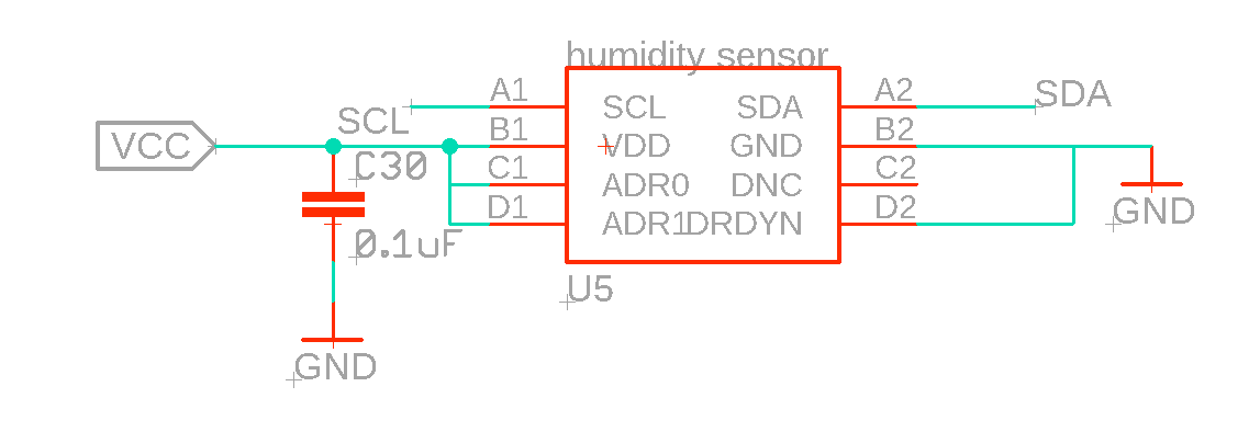
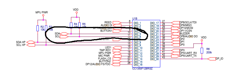
I was trying to configure the HDC1000 on sensor controller studio for cc1310 over i2c.

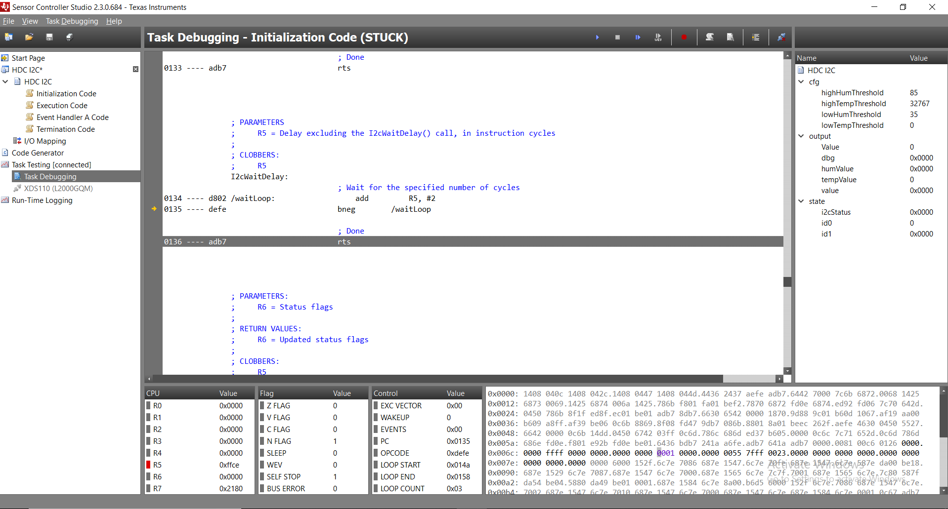
But i2c.status field always state as "1" mean that i2cstart(); is not working.

i used this thread for reference:

"https://e2e.ti.com/support/wireless-connectivity/sub-1-ghz/f/156/t/697646?tisearch=e2e-sitesearch&keymatch=HDC1000%20on%20sensor%20controller"

Can anyone help me with it.

  • Hi Himanshu,
    Will wait for the CC1310 team to reply on the I2C driver issue.
    From a humidity sensor perspective let me recommend to move to a newer device since HDC1000 is not recommended for new designs as can be read in the product page www.ti.com/.../HDC1000.

    Please consider the newest part HDC2010.

    Regards,
    Jose
  • Hello Himanshu,

    I am from the CC1310 team, I want to help you get your issue resolved.

    Can you please post your sensor controller project file, or post the code you are running?

    Make sure the mapping matches what you have connected on the HW. 

    DO you have the appropriate pull up resistors on the lines?

    Did you configure the clock to an acceptable rate by the HDC1000?

    If you can, post some scope shots of the SDA and SCL pins before and after the i2cStart call. The reason being that the only thing i2cStart does is clear the SDA pin wait for I2C_BASE_DELAY and then clear SCL pin.

    See below the disassembly of the I2Cstart();

                  I2cStart:
                                           ; SDA = driven low
    00fd ---- 460f                         iobclr      #(AUXIO_I2C_SDA & 0x7), [#(IOP_AIODIO0_GPIODOUT + (AUXIO_I2C_SDA >> 3))]
    
                                           ; Wait T_HD_STA
    00fe ---- 53f8                         ld          R5, #-((I2C_BASE_DELAY) - (1))
    00ff ---- 1502                         jsr         I2cWaitDelay
    
                                           ; SCL = driven low
    0100 ---- 450f                         iobclr      #(AUXIO_I2C_SCL & 0x7), [#(IOP_AIODIO0_GPIODOUT + (AUXIO_I2C_SCL >> 3))]
    
                                           ; Done
    0101 ---- adb7                         rts

                   ; PARAMETERS
                   ;     R5 = Delay excluding the I2cWaitDelay() call, in instruction cycles
                   ;
                   ; CLOBBERS:
                   ;     R5
                   I2cWaitDelay:
                                           ; Wait for the specified number of cycles
    0102 ---- d802 /waitLoop:                  add         R5, #2
    0103 ---- defe                         bneg        /waitLoop
    
                                           ; Done
    0104 ---- adb7                         rts

    Regards,

    AB

  • Hi Please find the code and schematic diagram for HDC1000 below:

    HDC_I2C_ADDR = 0x43

    Initialization code:

    i2cStart();
    
    i2cTx((HDC_I2C_ADDR << 1) | I2C_OP_WRITE);
    
    i2cTx(HDC_I2C_CONFIG_REGISTER);     // Config register
    
    i2cTx(0x10);     // MSB - bit 12 on
    
    i2cTx(0x00);
    
    i2cStop();
    
    fwScheduleTask(1);

    Execution code:

    i2cStart();
    
    i2cTx((HDC_I2C_ADDR << 1) | I2C_OP_WRITE);
    
    i2cTx(0x00);
    
    // If a measurement was successfully started during the last execution ...
    
    if (state.i2cStatus == 0x0000) {
    
       U16 tempValH;
    
       U16 tempValL;
    
       U16 humValH;
    
       U16 humValL;
    
       i2cRepeatedStart();
    
       i2cTx((HDC_I2C_ADDR << 1) | I2C_OP_READ);
    
       i2cRxAck(tempValH);
    
       i2cRxAck(tempValL);
    
       i2cRxAck(humValH);
    
       i2cRxNack(humValL);
    
       if (state.i2cStatus == 0x0000) {
    
           // Convert the result (4-bit exponent + 12-bit mantissa) into 16-bit fixed-point
    
           U16 tempVal;
    
           U16 humVal;
    
           tempVal = (tempValH << 6);
    
           tempVal |= (tempValL >> 2);
    
           humVal = (humValH << 6);
    
           humVal |= (humValL >> 2);
    
           output.tempValue = tempVal;
    
           output.humValue = humVal;
    
       }
    
    }
    
    i2cStop();
    
    fwDelayUs(2000, FW_DELAY_RANGE_1_MS);
    
    //Start the Task
    
    fwScheduleTask(1);

    Schematic diagram:

  • Try this:

    #define HDC_I2C_ADDR               0x43
    #define HDC_I2C_CONFIG_REGISTER    0x0002
    #define HDC_I2C_DATA_REGISTER      0x0000
    #define HDC_I2C_ID_REGISTER        0x00fe

    Initialization Code:

    // Read the HDC1000 ID to verify HW
    U16 found = 0;
    
    do {
        i2cStart();
        i2cTx((HDC_I2C_ADDR << 1) | I2C_OP_WRITE);
        i2cTx(HDC_I2C_ID_REGISTER);     // ID register
        
        if (state.i2cStatus == 0x0000) {
            i2cRepeatedStart();
            i2cTx((HDC_I2C_ADDR << 1) | I2C_OP_READ);
            i2cRxAck(state.id0);
            i2cRxNack(state.id1);
    
        
            if (state.id0 == 0x0054) {
                if (state.id1 == 0x0049) {
                    found = 1;
                }
            }   
         }
         i2cStop();    
    } while (found == 0);
    
    i2cStart();
    i2cTx((HDC_I2C_ADDR << 1) | I2C_OP_WRITE);
    i2cTx(HDC_I2C_CONFIG_REGISTER);     // Config register
    i2cTx(0x10);                        // MSB - bit 12 on
    i2cTx(0x00);
    i2cStop();
    
    //Start the Task
    fwScheduleTask(1);

    Execution Code:

    i2cStart();
    i2cTx((HDC_I2C_ADDR << 1) | I2C_OP_WRITE);
    i2cTx(HDC_I2C_DATA_REGISTER);     // Data register
    i2cStop();
    
    // Sleep 26 miliseconds then start event
    evhSetupTimer1Trigger(0, 26, 2);

    Event Handler A Code:

    i2cStart();
    i2cTx((HDC_I2C_ADDR << 1) | I2C_OP_READ);
    
    if (state.i2cStatus == 0x0000) {
        U16 tempValH;
        U16 tempValL;
        U16 humValH;
        U16 humValL;
        
        // Read the result
        i2cRxAck(tempValH);
        i2cRxAck(tempValL);
        i2cRxAck(humValH);
        i2cRxNack(humValL);
        
        if (state.i2cStatus == 0x0000) {
            // Convert the result (4-bit exponent + 12-bit mantissa) into 16-bit fixed-point
            U16 tempVal;
            U16 humVal;
            tempVal = (tempValH << 6);
            tempVal |= (tempValL >> 2);
            humVal = (humValH << 6);
            humVal |= (humValL >> 2);
            
            output.tempValue = tempVal;
            output.humValue = humVal;
            
            // Notify the application when the result is below the low threshold or above the high threshold
            if (humVal < cfg.lowHumThreshold) {
                fwGenAlertInterrupt();
            } else if (humVal > cfg.highHumThreshold) {
                fwGenAlertInterrupt();
            }
            if (tempVal < cfg.lowTempThreshold) {
                fwGenAlertInterrupt();
            } else if (tempVal > cfg.highTempThreshold) {
                fwGenAlertInterrupt();
            }
        }
    }
    i2cStop();
    
    fwScheduleTask(1);

    Termination Code:

    evhCancelTrigger(0);

    Make sure you have 'Timer 1 Event Trigger' selected in project properties, and if you done changes in PCB in I2C lines length you can adjust 'I2C SCL stretch timeout' for slow/faster SCL clock rate.

    Also, note that I put 

    fwScheduleTask(1);

    In event handler code and not in the execution code.. I don't know if this is the correct approach, but it is ok for my needs...

  • Hi,

    I have tried the above given code but my execution got struck on initiation code itself, can you please have a look on it:

    Given below is the screenshot of error and HDC_cfg.:

  • Are you using evaluation board or custom board?

    Can you post your I/O Mapping?

    Is the main CPU using i2c driver?

  • we are using custom board.
    I/O Mapping:
    cc1310 SDA pin <----> A2(HDC1010)
    cc1310 SCL pin <-----> A1(HDC(1010)

    Yes main cpu use i2c driver
  • Himanshu Gupta25 said:
    I/O Mapping:
    cc1310 SDA pin <----> A2(HDC1010)
    cc1310 SCL pin <-----> A1(HDC(1010)


    I meant the I/O mapping in Sensor Controller Project. Above 'Code Generator' tab there is 'I/O mapping' tab where you map your IO pins (I2C in this case) to DIO pins on CC1350 cpu.. If you attach picture of SDA and SCL lines to the CC1350 cpu, I maybe can help with that. In the evaluation board:


    Then in Sensor Controller:


    Himanshu Gupta25 said:
    Yes main cpu use i2c driver

    Try disable all usage of I2C in application first. Don't use I2C_Open or any other I2C functions, add it after you have the sensor controller application working...

  • Hi,

    Can you please check I/O mapping in sensor controller is: