This thread has been locked.

If you have a related question, please click the "Ask a related question" button in the top right corner. The newly created question will be automatically linked to this question.

AWR1243: AWR1243 SPI Clock Issue

Part Number: AWR1243
Hi Scott,
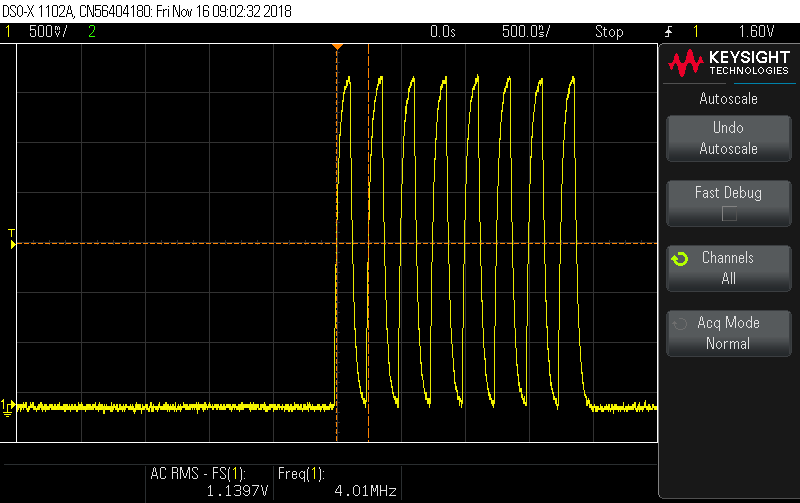
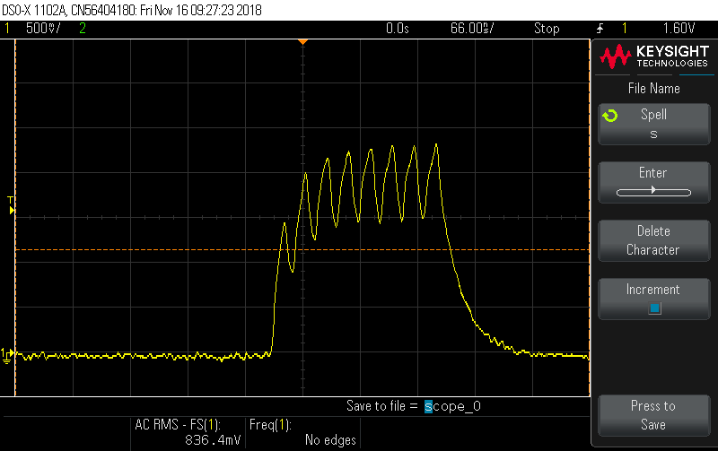
We need hardware support on the problem we see here. We spun a custom AWR1243 board based on the D3 Satellite Radar Module design and are trying to flash the firmware on the board (radarss.bin, masterss.bin and the config.bin from the Vision SDK) and encountered an issue with the SPI clock coming out of the AWR1243. Please see attached pics. The clean clock pic was taken from the D3 board and the other pic was taken from our AWR1243 custom board.
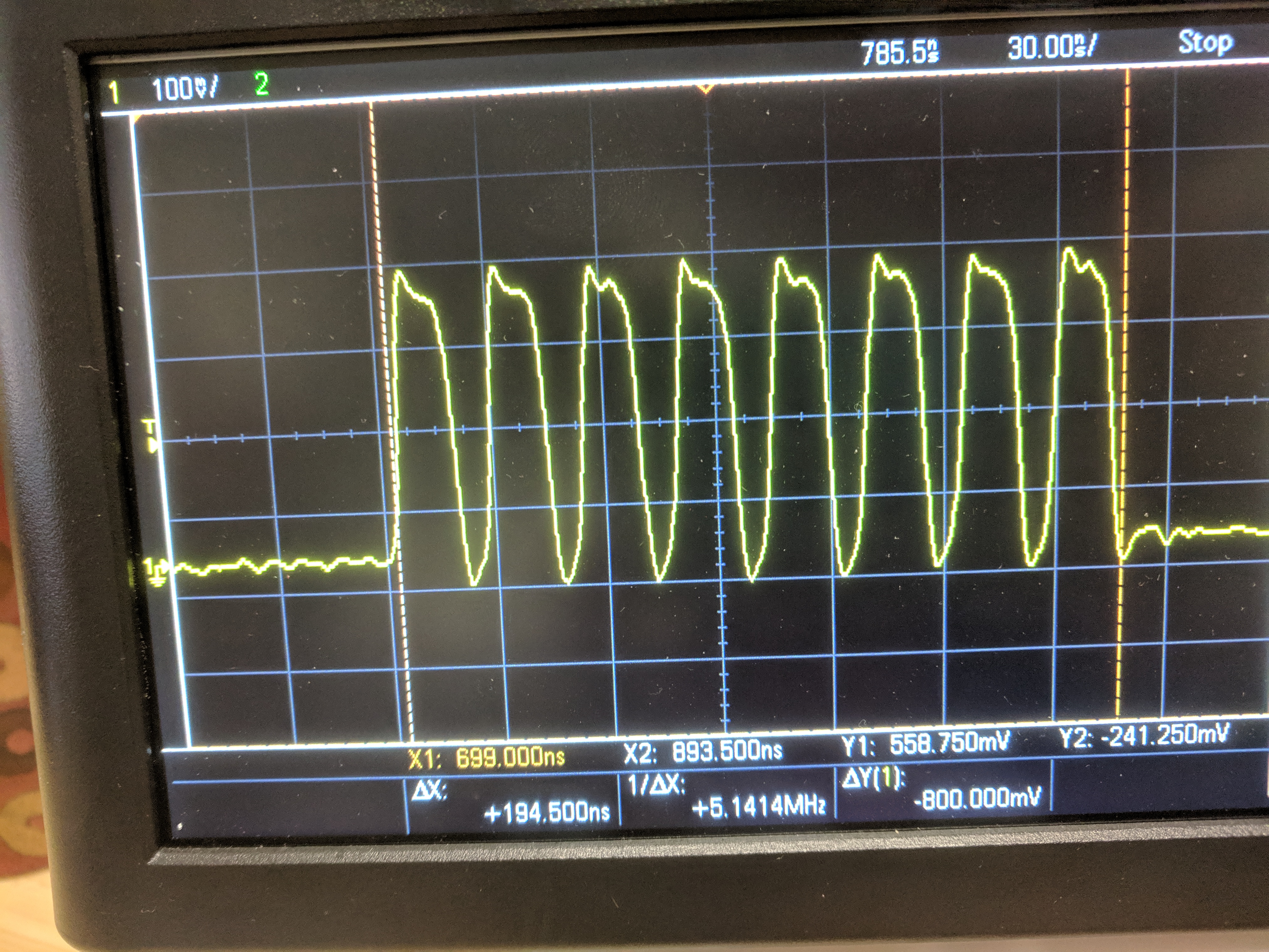
On D3 board we can see a clean clock coming out of AWR1243 at 4MHz with 3.3V magnitude. On our board we see 40MHz clock that is clean but not correct with magnitude of 2.5V. At this point we don't know why there is such a discrepancy in clock frequency and why it was distorted the way it exhibited. 
On D3 board there is a 22Ohm resistor in series with 8pF max capacitor foing into Cypress flash chip SPI input clock. We tried different resistor values (1Ohm and 82Ohm) but have the same results.
We will appreciate any help.
Thanks,
--Khai
  •   Forgot to attache the clock pics.

  • Hi Khai, 

    Just two immediate thoughts: 

    1. Please verify you are following the TI AWR1243 Boosterpack and/or D3 netlist and BOM on this QSPI flash memory interface -- any differences at all?

    2. Can you please describe any differences between this custom system and the TI AWR1243 Boosterpack and/or D3 design?

    Thanks,

    -Randy

  • Hi Randy,

    This is Tom from Metawave. To answer to your questions 

    1) We are following D3 netlist and BOM. In fact we have not made any changes on parts and shematic and PCB layout.

    2) We used different stack up and dielectric for board however at this moment it does not explain why we are measuring clock 10 times faster on our board compare to D3 board. (please see attached pictures)

    We need to get to the bottom of this and and as Bhavin mentioned we are counting on your help.

    Thank you 

    Tom    

  • BTW first 2 pics are from D3 board and last one from Metawave board.
  • Hi Tom,

    Just coming back from Thanksgiving Holiday. I did not noticed the frequency difference initially. I am going to follow up internally with our ROM designer. I will probably need a few days to get a response back to you.

    Thank you,
    -Randy
  • Hi Tom,

    Can you please confirm the exact revision of device used in both of these cases?

    Talking to our boot ROM team I think this may actually be intended operation. Depending on when the devices were sampled for the D3 board being referenced, the 4 MHz QSPI clock is expected for older AWR1243 ES2.0 samples. The 40 MHz QSPI clock is expected for current AWR1243 ES3.0 samples.

    Also, judging from the different oscilloscope shots, it appears that there is nothing wrong with this clock other than the difference in anticipated frequency. The first scope may have not had sufficient probe or input bandwidth relative to the second. Can you please confirm that the clock signal integrity looks good with the higher bandwidth scope? This would change the QSPI clock constraints of the attached QSPI flash memory as well.

    Thank you,
    -Randy
  • Hi Randy,

    This is Khai from Metawave working with Tom on the same issue. The issue has been solved. We used ES3.0 version and the chip has been flashed with respective FW. It's up and functional.

    Thanks for the support,

    --Khai

  • Hi Khai,

    Sounds good. Can you please verify the issue is resolved using the post options here?

    Thank you,
    -Randy