This thread has been locked.

If you have a related question, please click the "Ask a related question" button in the top right corner. The newly created question will be automatically linked to this question.

PGA460: SCLK tied to GND or GNDP?

Part Number: PGA460

Hi,

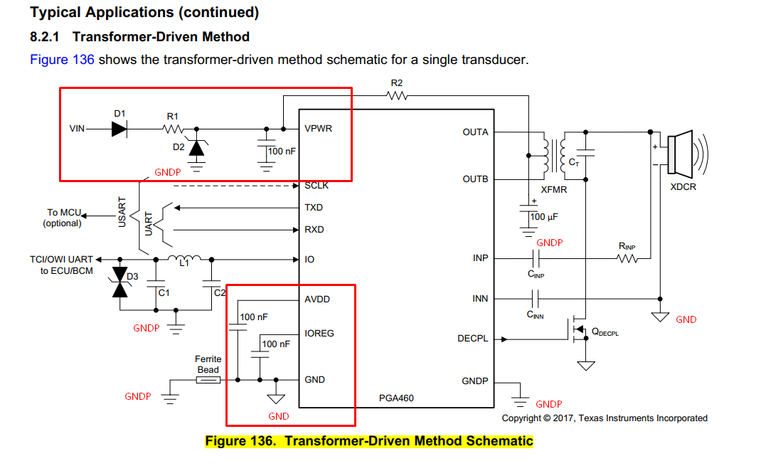
I know that If you don't use SCLK, it has to be tied to GND, but In the schematic reference, there are two different kind of GNDs: GND and GNDP, Which one is the right GND?

Best regards

  • Hi Oscar,

    If both GND and GNDP are common (which they ultimately need to be), then it doesn't matter.

    I will generally recommend  that you pull SCLK low to GND (pins 1 and 4 shorted internally). GNDP is mainly used for grounding the IO transceiver internally, and it's supporting external passives (if applied). Isolating the IO transceiver ground (GNDP), the transducer/sensor ground (GNDX - optionally created externally), and general GND is typical for automotive systems, so your non-auto design may not be as sensitive to the various ground cases.

    You can see a schematic/layout example of the automotive grounding requirements in the ultra small form factor mono static transformer driven reference design on the Design Files section of the PGA460's Technical document page. Otherwise, you can merge all grounds into a single ground throughout the layout to simplify routing.

  • Hi Akeem,

    I think there is an error in the datasseet because it doesn't match with the PGA460Q1USFF_XFMR.SchDoc (PGA460 Mono-static Transducer Transformer Driver Ultra-Small Design File).

    Here is the typical application:

    And here is the PGA460 Mono-static Transducer Transformer Driver Ultra-Small Design File:

    If you compare the GNDs designation they are completely different. Which one is the right designation?

    Best regards.

  • Hi Oscar,

    The reference design schematic is most accurate and has been proven effective in performance and stress testing. Here, all three grounds (device ground, power/IO ground, and sensor ground) are represented with unique designators. More importantly, for automotive considerations, is this reference design's layout consideration and example for ESD robustness.

    The typical application schematic from the datasheet intends to depict and separate sensor ground from the remaining grounds (device and power/IO). We can update the datasheet for a more accurate representation. This datasheet illustration corresponds to the first layout guideline bullet from section 10.1 of the datasheet:

    "Separating the grounding types is important to reduce noise at the AFE input of the PGA460-Q1. In particular, the transducer sensor ground, supporting driver, and return-path circuitry should have a separate ground before being connected to the main ground. Separating the sensor and main grounds through a ferrite bead is best practice, but not required; a copper-trace or 0-Ω short is also acceptable when bridging grounds."

    We will update the datasheet schematic to match the reference design's grounding to avoid confusion. Thanks for bringing this to our attention.
  • Ok,

    I appreciate it.

    Thank you very much.