This thread has been locked.

If you have a related question, please click the "Ask a related question" button in the top right corner. The newly created question will be automatically linked to this question.

IWR1443: rangeDopplerLogMagMatrix data comparison with fftOut1D data

Part Number: IWR1443
Other Parts Discussed in Thread: MMWAVE-SDK,

Hi,

I have compared the data in rangeDopplerLogMagMatrix which is sent to the visualizer gui to the data in fftOut1D.  The comparison is done after clutter removal and the code used for the comparison is similar to

    MmwDemo_process2D(dataPathObj);
    for (rngIdx = 0; rngIdx < dataPathObj->numRangeBins; rngIdx++)
      {
        a1 = fftOut1D[rngIdx*(dataPathObj->numDopplerBins)].real;
        a2 = fftOut1D[rngIdx*(dataPathObj->numDopplerBins)].imag;
        mag_sq = a1*a1 + a2*a2;
        System_printf("mag_sq, zero doppler %d %d\n",mag_sq, dataPathObj->>rangeDopplerLogMagMatrix[rngIdx*dataPathObj->numDopplerBins]);
      }

I obtain believable results from the fftOut1D data but not from the rangeDopplerLogMagMatrix data.  The rangeDopplerLogMagMatrix data does not indicate the location of the expected scattering centers as does the fftOut1D data does.  Naturally, the gui graphical out produces the correct results.  I'm I missing some processing steps?

Thanks for the help.

Al

  • Hi Allen,

    I'm not sure I understand your objective but the comparison is not valid.

    The Radar Cube contains the 1D-FFT output for all chirps and all virtual antennas, while the Range-Doppler Log Matrix is generated after performing 2D FFT (Doppler FFT) on the 1D FFT output for each virtual antenna and then performing a sum of the corresponding log2 magnitudes of all virtual antennas.

    At a high level, each Range-Doppler cell of the 2D fft output contains an array of virtual antennas (each sample is complex 16-bit). Each Range-Doppler detection matrix cell is the sum of the log2 magnitudes of the virtual antennas of the Range-Doppler cell. i.e if the virtual antenna array for each Range-Doppler cell is x[i], i = 0..N-1 (N = virtual antennas), then detection matrix Range-Doppler cell = sum i = 0..N-1 {log2|x(i)|).

    There is also format difference between the 1D-FFT output (16-bit complex) and Range-Doppler Log Magnitude matrix (16-bit real) due to fixed point conversion and scaling.

    Please refer to the 14xx mmw demo doxygen documentation for detailed description of the OOB demo processing chain. This is available in the MMWAVE-SDK at

    C:\ti\mmwave_sdk_02_01_00_04\packages\ti\demo\xwr14xx\mmw\docs\doxygen\html\index.html

    Regards

    -Nitin 

  • Hi Nitin,

    Thank you for your reply. I am familiar with the high level discussion presented in

    C:\ti\mmwave_sdk_02_01_00_04\packages\ti\demo\xwr14xx\mmw\docs\doxygen\html\index.html

    I guess I should define what I mean my comparison.  I am aware that the 1d-fft output is 16 bit complex and the range doppler log magnitude is 16 bit real.  This just means the 1d-fft output just has to have is complex absolute value generated for comparison purposes and a log2 then as well.  But how?

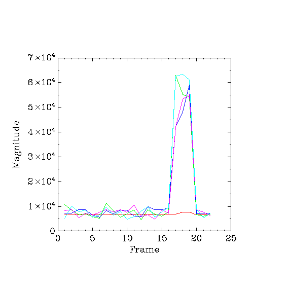
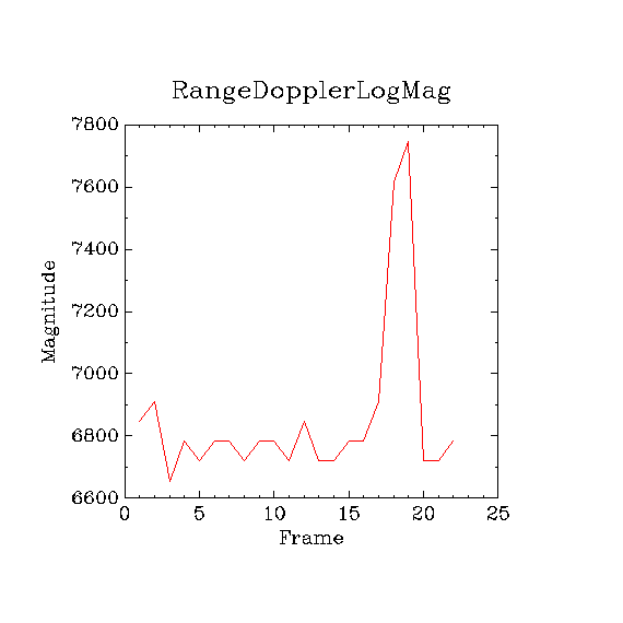
    I had done a little experiment last week with the sensor configured with just one antenna and four chirps per frame.  I had a scatterer move in front of the sensor and I collected 25 frames. I then selected the peak magnitudes for the four chirps per frame from the 1d-ouput.  I had also selected the peak maglog values in the rangedopplerlogmagnitude array.  These values are shown in figure comp.gif.  The red curve is the rangedopplerlogmagnitude data and the other four curves are the 1d-fft data.  Figure rangeDoppler.gif contains just the rangedopplerlogmagnitude by itself.  Yes, the peak value for each point in the comp.gif plot will not be at the same range index value but close to it.  The include code illustrates how I arrived at the plotted data.

    I just do not see how summing over the 1d-fft data using sum i = 0..N-1 {log2|x(i)|) will yield the data in the rangedopplerlogmagnitude array (in my example N=4).  I believe the values for the rangedopplerlogmagnitude array are generated in the *radarss.bin program which I do not have the source code for.

    Can you please provide me with the part(s) I am missing?

    Thanks.

    Al

            MmwDemo_process2D(dataPathObj);
            /* 2nd Dimension FFT done! */
        mag0=0;
        mag1=0;
        mag2=0;
        mag3=0;
        mag4=0;    
        for(i = 0; i < dataPathObj->numRangeBins; i++)
            {
          a1=fftOut1D[i*dataPathObj->numDopplerBins].real;
          a2=fftOut1D[i*dataPathObj->numDopplerBins].imag;
          mag=a1*a1+a2*a2;
          if(mag>mag1)
            {
              mag1=mag;
            }
          a1=fftOut1D[i*dataPathObj->numDopplerBins+1].real;
          a2=fftOut1D[i*dataPathObj->numDopplerBins+1].imag;
          mag=a1*a1+a2*a2;
          if(mag>mag2)
            {
              mag2=mag;
            }          
          a1=fftOut1D[i*dataPathObj->numDopplerBins+2].real;
          a2=fftOut1D[i*dataPathObj->numDopplerBins+2].imag;
          mag=a1*a1+a2*a2;
          if(mag>mag3)
            {
              mag3=mag;
            }
          a1=fftOut1D[i*dataPathObj->numDopplerBins+3].real;
          a2=fftOut1D[i*dataPathObj->numDopplerBins+3].imag;
          mag=a1*a1+a2*a2;
          if(mag>mag4)
            {
              mag4=mag;
            }
          if(dataPathObj->rangeDopplerLogMagMatrix[i*dataPathObj->numDopplerBins]>mag0)
            {
              mag0=dataPathObj->rangeDopplerLogMagMatrix[i*dataPathObj->numDopplerBins];
              ind0=i;
            }
        }
        System_printf("%d %d %d %d %d\n",mag0,mag1,mag2,mag3,mag4);

  • Hi Allen,

    @Allen: I believe the values for the rangedopplerlogmagnitude array are generated in the *radarss.bin program which I do not have the source code for.

    The Radar Hardware Accelerator on board the IWR1443 device is used for the FFT and LogMagnitude operations and it is programmed in the MSS application code itself. Please look at the Radar Hardware Accelerator training video under mmwave-training-series for an introduction. For more details, refer to the Radar Hardware Accelerator user guide.

    Regards

    -Nitin

  • Hi Nitin,

    Thank you for the links.  I will look at the hardware accelerator document.

    Al