This thread has been locked.

If you have a related question, please click the "Ask a related question" button in the top right corner. The newly created question will be automatically linked to this question.

PGA460-Q1: After a period of time, the maximum measurement distance of the ultrasonic test becomes shorter

Part Number: PGA460-Q1
Other Parts Discussed in Thread: PGA460

Hi

We are a company that develops robots,We have designed a PCB board for ultrasonic detection distance, including PGA460 and MA58MF14-7N. Our goal is to detect the distance of 10cm~3m in front of the robot. Now we have encountered some problems, we hope to get your reply.

1.The nearest distance can only be detected at 25cm, and the distance below 25cm is incorrect

2.After a period of use, the maximum detection distance changes from 3m to 60cm (the distance beyond 60cm cannot be detected, it feels like there is something at 60cm) or 30cm or other distances less than 3m. After reconfiguration of PGA460 parameters, it returns to normal


The distance data I get is the data from Preset1 by running burst&listen.

The following are our own design of hardware and configuration parameters of PGA460:

The software parameters:

;GRID_USER_MEMSPACE
 (USER_DATA1),00
 (USER_DATA2),00
 (USER_DATA3),00
 (USER_DATA4),00
 (USER_DATA5),00
 (USER_DATA6),00
 (USER_DATA7),00
 (USER_DATA8),00
 (USER_DATA9),00
 (USER_DATA10),00
 (USER_DATA11),00
(USER_DATA12),00
 (USER_DATA13),00
 (USER_DATA14),00
 (USER_DATA15),00
(USER_DATA16),00
 (USER_DATA17),00
 (USER_DATA18),00
 (USER_DATA19),00
 (USER_DATA20),00
 (TVGAIN0),8D
 (TVGAIN1),EE
 (TVGAIN2),EF
 (TVGAIN3),10
 (TVGAIN4),A5
 (TVGAIN5),20
 (TVGAIN6),C0
 (INIT_GAIN),40
 (FREQUENCY),8F
 (DEADTIME),00
(PULSE_P1),10
 (PULSE_P2),12
 (CURR_LIM_P1),5C
 (CURR_LIM_P2),7F
 (REC_LENGTH),8C
 (FREQ_DIAG),00
 (SAT_FDIAG_TH),EE
 (FVOLT_DEC),7C
 (DECPL_TEMP),0A
 (DSP_SCALE),00
 (TEMP_TRIM),00
 (P1_GAIN_CTRL),08
 (P2_GAIN_CTRL),00
 (EE_CRC),84
 (EE_CNTRL),00
 (BPF_A2_MSB),8A
 (BPF_A2_LSB),0C
 (BPF_A3_MSB),F9
 (BPF_A3_LSB),A5
 (BPF_B1_MSB),03
 (BPF_B1_LSB),2D
 (LPF_A2_MSB),7E
 (LPF_A2_LSB),67
 (LPF_B1_MSB),00
 (LPF_B1_LSB),CD
 (TEST_MUX),00
 (DEV_STAT0),80
 (DEV_STAT1),00
 (P1_THR_0),88
 (P1_THR_1),88
 (P1_THR_2),88
 (P1_THR_3),88
 (P1_THR_4),88
 (P1_THR_5),88
 (P1_THR_6),84
 (P1_THR_7),21
 (P1_THR_8),08
 (P1_THR_9),42
 (P1_THR_10),10
 (P1_THR_11),80
 (P1_THR_12),80
(P1_THR_13),80
 (P1_THR_14),80
 (P1_THR_15),00
 (P2_THR_0),77
 (P2_THR_1),77
 (P2_THR_2),77
 (P2_THR_3),77
 (P2_THR_4),78
(P2_THR_5),88
 (P2_THR_6),9C
 (P2_THR_7),D0
 (P2_THR_8),72
 (P2_THR_9),10
(P2_THR_10),63
 (P2_THR_11),28
 (P2_THR_12),30
 (P2_THR_13),34
 (P2_THR_14),3C
 (P2_THR_15),00
 (THR_CRC),AE
EOF


T1&T2: TDK_B78416A2232A003

R9&R18: 2.7k

C5&C18: 1500pF

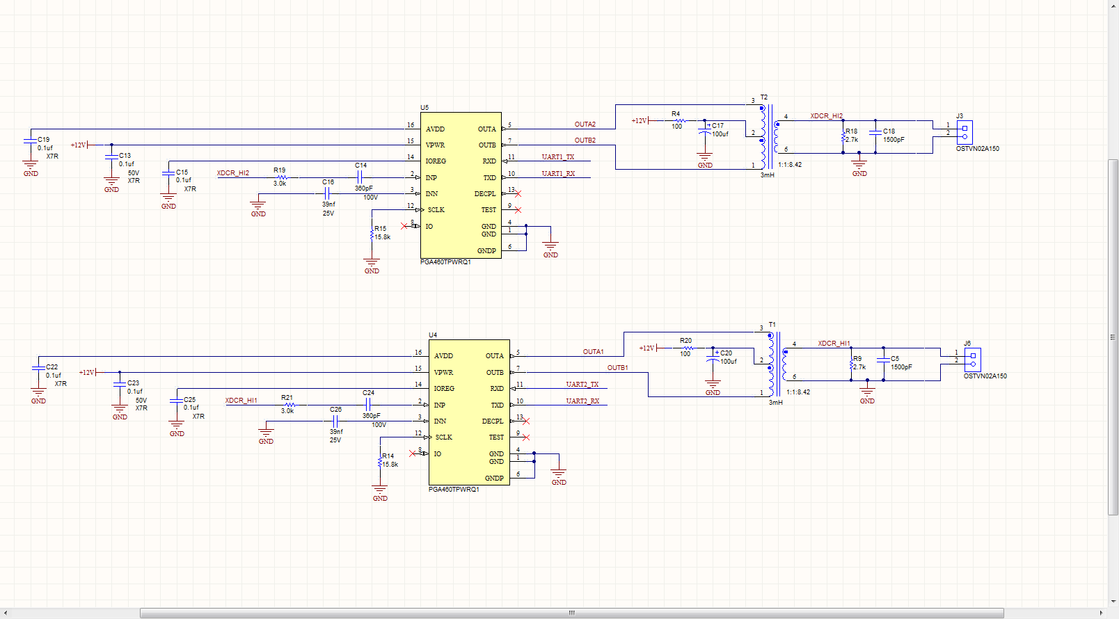
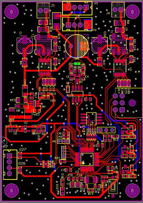
The two transducers on the PCB board correspond to the front and right of the robot respectively

Best Wishes

  • Hi Jony,

    Thanks for providing all the details of your hardware and software. You appear to be using the same HW settings and SW configuration as the EVM, which may not be the best approach for your robot applicaiton. Here are my recommendations to help you achieve 10cm~3m object detection:

    1) Consider using a higher frequency transducer in the 70~80kHz range. The Murata MA58MF14-7N is intended for automotive park assist applications ranging up to 5~7m. For a list of transducer part numbers you can filter by frequency, field-of-view, excitation voltage, etc., see the transducer-transformer E2E discussion at: e2e.ti.com/.../620399

    2) If you are to continue using the Murata transducer, you should re-optimize the values of the matching circuit (your schematic's R18, C18, R9, C5) in parallel to the transducer. The re-optimized values are mentioned in the datasheet ( www.ti.com/.../pga460-q1.pdf ) section 8.2.1.3 Application Curves:
    Components used: TDK EPCOS B78416A2232A003 Transformer, muRata MA58MF14-7N transducer. To
    minimize the ranging of the TDK EPCOS B78416A2232A003 transformer and muRata MA58MF14-7N
    transducer combination, place a 680pF tuning capacitor (CT) and 10kΩ damping resistor (RDamp) in parallel to the
    transducer. This will enable sub-15cm ranging depending on the pulse count, center-tap voltage, and driver
    current limit.
    For a better understanding of how these matching circuit impacts short range performance, see the "PGA460 Ultrasonic Module Hardware and Software Optimization" appnote ( www.ti.com/.../slaa732 ) section 3.4.

    3) The Murata transducer can only achieve 10cm if you reduce the pulse count, driver current limit, initial time varying gain, and/or supply voltage. Based on your existing GUI settings of a 58-90dB range, you will not be able to see below 25cm. You need to change the gain range to 32.5-64dB to improve short range detection down towards 10cm. Since these default settings were intended to reach +5m, you should reduce you pulse count to half of what you are using now (from 18 to ~9). For a better understanding of how these PGA460 variables impact short range performance, see the "PGA460 Ultrasonic Module Hardware and Software Optimization" appnote ( www.ti.com/.../slaa732 ) section 4.

    4) Your preset 1 threshold is at the midcode level, which would be sufficient for 30cm to 5m detection, but because you need downwards of 10cm, you will likely need to optimize and wrap your threshold with more precision. You can either manually optimize the threshold as descrbe in section 5.3 of the PGA460 FAQ ( www.ti.com/.../slaa733.pdf ), or you can use the Auto-Threshold feature on the Threshold page of the GUI. You can see a video demonstration of the manual threshold optimization procedure at: training.ti.com/pga460-ultrasonic-sensing-evm-gui-data-monitor

    5) Because 10cm may require a very low pulse count, you may need to switch between preset 1 and 2, such that preset 1 is used exclusively for very short range detection (10cm~50cm), while preset 2 is used for the remainder (25~3m).

    6) I'd need to see your echo data dump result to debug the 60cm false positive, but I suspect that because you are using a fixed threshold, the ringing decay is crossing the threshold more than once on occasion due to the high TVG gain. After you optimize the threshold, you should not see any more false positives.
  • Dear AKeem

    Thank you for your reply, 

      I configured the PGA460 the following way:

     initThresholds(huart,fixedThr);

     defaultPGA460(huart,Transducer);

     runDiagnostics(huart,1,0);

     runDiagnostics(huart,0,1);

    runDiagnostics(huart,0,2);

    runDiagnostics(huart,0,3);

    runEchoDataDump(huart,edd-1);

    pullEchoDataDump(huart,0);

    The way I get the distance is:

    ultrasonicCmd(&huart1,0,numObj,1);  // numObi is 2
    HAL_Delay(30);

    pullUltrasonicMeasResult(huart);

    distance = printUltrasonicMeasResult(huart,0);

    The above configuration reference EVM source code

    my echo data dump result:   0,0,0,0,0,0,0,0,0,0,0,0,0,0,0,0,0,0,0,0,9a, ab, bd,e7, 5e, f5,9c, 5C, 8f, 00, 10, 04, 5C,7F, 41, 00, EE, 7C, 0A, 0, 0, 08,

    0,11,8C,38,0C,61,F2,28.BA,E3,77,36,D7,2F,87,9E,2A,4D,18,CE,00,3B,08,31,AD,B0,38,AD,B5,34,39,D2,9E,5F,9B,B0,2E,2D,C2,B1,F1,3D,C3,AC,

    DF,7F,00,E3,31,AD,66,41,94,FE,63,27,00,3F,18,E1,10,D7,71,00,E1,27,BE,BD,69,37,32,A9,D5,1D,18,F3,11,F8,31,BE,CE,78,77,0,0,0,0,0

    The value of the register read after configuration is complete

    (USER_DATA1),00
     (USER_DATA2),00
     (USER_DATA3),00
     (USER_DATA4),00
     (USER_DATA5),00
     (USER_DATA6),00
     (USER_DATA7),00
     (USER_DATA8),00
     (USER_DATA9),00
     (USER_DATA10),00
     (USER_DATA11),00
    (USER_DATA12),00
     (USER_DATA13),00
     (USER_DATA14),00
     (USER_DATA15),00
    (USER_DATA16),00
     (USER_DATA17),00
     (USER_DATA18),00
     (USER_DATA19),00
     (USER_DATA20),00
     (TVGAIN0),9A
     (TVGAIN1),AB
     (TVGAIN2),BD
     (TVGAIN3),E7
     (TVGAIN4),5E
     (TVGAIN5),F5
     (TVGAIN6),9C
     (INIT_GAIN),5C
     (FREQUENCY),8F
     (DEADTIME),00
    (PULSE_P1),10
     (PULSE_P2),04
     (CURR_LIM_P1),5C
     (CURR_LIM_P2),7F
     (REC_LENGTH),41
     (FREQ_DIAG),00
     (SAT_FDIAG_TH),EE
     (FVOLT_DEC),7C
     (DECPL_TEMP),0A
     (DSP_SCALE),00
     (TEMP_TRIM),00
     (P1_GAIN_CTRL),08
     (P2_GAIN_CTRL),00
     (EE_CRC),D4
     (EE_CNTRL),00
     (BPF_A2_MSB),8A
     (BPF_A2_LSB),0C
     (BPF_A3_MSB),F9
     (BPF_A3_LSB),A5
     (BPF_B1_MSB),03
     (BPF_B1_LSB),2D
     (LPF_A2_MSB),7E
     (LPF_A2_LSB),67
     (LPF_B1_MSB),00
     (LPF_B1_LSB),CD
     (TEST_MUX),00
     (DEV_STAT0),80
     (DEV_STAT1),00
     (P1_THR_0),88
     (P1_THR_1),88
     (P1_THR_2),88
     (P1_THR_3),88
     (P1_THR_4),88
     (P1_THR_5),88
     (P1_THR_6),84
     (P1_THR_7),21
     (P1_THR_8),08
     (P1_THR_9),42
     (P1_THR_10),10
     (P1_THR_11),80
     (P1_THR_12),80
    (P1_THR_13),80
     (P1_THR_14),80
     (P1_THR_15),00
     (P2_THR_0),88
     (P2_THR_1),88
     (P2_THR_2),88
     (P2_THR_3),88
     (P2_THR_4),88
    (P2_THR_5),88
     (P2_THR_6),84
     (P2_THR_7),21
     (P2_THR_8),08
     (P2_THR_9),42
    (P2_THR_10),10
     (P2_THR_11),80
     (P2_THR_12),80
     (P2_THR_13),80
     (P2_THR_14),80
     (P2_THR_15),00
     (THR_CRC),28

    Thanks