This thread has been locked.

If you have a related question, please click the "Ask a related question" button in the top right corner. The newly created question will be automatically linked to this question.

DCA1000EVM: Automated frame triggering

Part Number: DCA1000EVM
Other Parts Discussed in Thread: AWR1642BOOST, AWR1243, AWR1642

Hello,

I have a AWR1642Boost together with a DCA1000EVM and would like to record data in a controlled setup,
e.g. I need to know *when* a frame was captured. For this I started with the following procedure:

1) connect to the DCA1000 via mmwave Studio (although I would like to get rid of mmwave Studio if possible...)

2) register a python script at socket 192.168.33.30:4098 to fetch the adc data

3) run a customized version of the DataCaptureDemo_xWR.lua in mmwave Studio which stops just before the 'ar1.StartFrame()'

4) automated triggering of multiple frames from a python script.

While steps 1-3 work fine, I do not know how to externally trigger frames. If I trigger a frame from the lua shell via ar1.StartFrame()
I can afterwards re-start the recording by sending 0x05 to socket 192.168.33.30:4096 - although I do not want to end recording
after the frame trigger in the first place.

Can you tell me if there is a similar way to trigger the frame start? Maybe send some Message via the COM-port directly to the xWR device?
Can you give me a rough estimate on the time delay between frame trigger and the actual frame?
Would it be smaller or at least more systematic then the delay between the frame and the arrival of the udp-package on the host?

Best regards.

  • Hi,

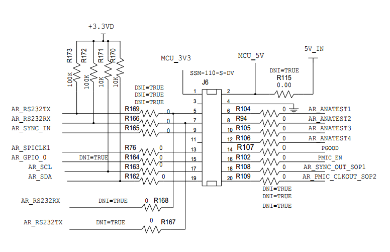
    You could consider using the device with an external hardware trigger. The device will accept a hardware trigger pulse on the SYNC_IN pin. You may need to populate resistor R165 on the AWR1642BOOST board to be able to provide this signal from the J6 connector.

    If you're using mmWaveStudio, then on the frame config section on the SensorConfig tab you will need to select Hardware Trigger instead of Software trigger, and then the Start Frame button as usual. The device will wait for a pulse on the SYNC_IN pin before starting framing. You will need to provide one trigger pulse for each frame.

    The delay between the trigger pulse and the start of the frame is also programmable.

    Best Regards,
    Anand
  • Hi,

    Thanks for the reply. What exactly do you mean by "populate resistor R165"?

    How would I do that?

    Kind Regards

  • Hi,

    The following screenshot from the schematic shows the j6 connector and the signals going from it. R165 is a resistor in the path of the AR_SYNC_IN signal between the AWR1243 and the J6 connector. R165 is marked DNI, which means it is just a placeholder and is not installed by default on the PCB. If you wish to make use of the J6 connector to provide the trigger pulse to the AWR1243, then you will need to solder a 0 ohm resistor on the PCB where R165 should be.

    Best Regards,

    Anand

  • Hi,
    thanks for the clarification, but unfortunately I can't see any screenshot... Is this a problem on my side(?)
  • Hi,

    Looks like the screenshot did not get added to the post.

    Please find it attached.

    Best Regards,

    Anand

  • Hi,

    Thank you for the support!
    We soldered a 100 Ohm resistor into R165.
    Unfortunately, this did not work, the DCA1000 gets a (timeout)
    error after 30sec and does not react to the trigger signal.

    [11:18:01] [RadarAPI]: ar1.StartFrame()
    [11:18:01] [RadarAPI]: Status: Passed
    [11:18:01]
    [11:18:01] ***Script completed successfully.***
    [11:18:01] Frame start async event received!
    [11:18:30] [RadarAPI]: STS_NO_LVDS_DATA Async event recieved(0)

    Also the LEDs 1 (DATA_TRANS_PROG_LED1) and 7 (LVDS_PATH_ERR_LED3) on the DCA1000 board turn on.

    We chose 100 instead of 0 Ohm for safety reasons as AR_SYNC_IN seems to be also connected to the J1 HD Connector via 0 Ohm Resistor (R62)...

    The 3.3V trigger signal gets "pulled down" to ~700mV, although we have configured HW-trigger in mmwave studio.
    Therefore we replaced the Resistor R62 on the AWR1642 by a 510 Ohm Resistor.
    This now works.
    Just for curiosity, is this really the intended way to get HW triggered frame recording?

    Furthermore, these modifications were done in a rev. A eval board AWR1642 (the R165 was not populated).
    But in our rev. B eval board R165 is populated...

    Kind Regards.
  • Hi,

    I missed the R62 connection - the J1 connector wasn't used in our previous capture solution with the MMWAVE-DEVPACK board instead of the DCA1000.

    The DCA1000 should not have been driving this signal but does seem to be doing so in the present design.

    So the recommended modifications should have been remove R62 and install R165.
    I will check about R165 being populated already on the RevB boards - I wasn't expecting this change.

    Best Regards,
    Anand