This thread has been locked.

If you have a related question, please click the "Ask a related question" button in the top right corner. The newly created question will be automatically linked to this question.

CCS/IWR6843: DSP Project Creation failure

Part Number: IWR6843
Other Parts Discussed in Thread: MMWAVEICBOOST, UNIFLASH, IWR1642

Tool/software: Code Composer Studio

Dear Team,

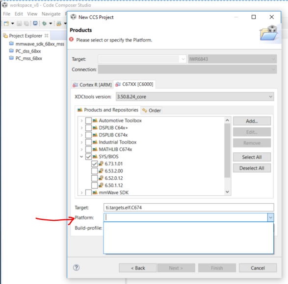
1. I'm trying to create a project for DSP Core, in this process CCS8 is not detecting the IWR6843 platform.

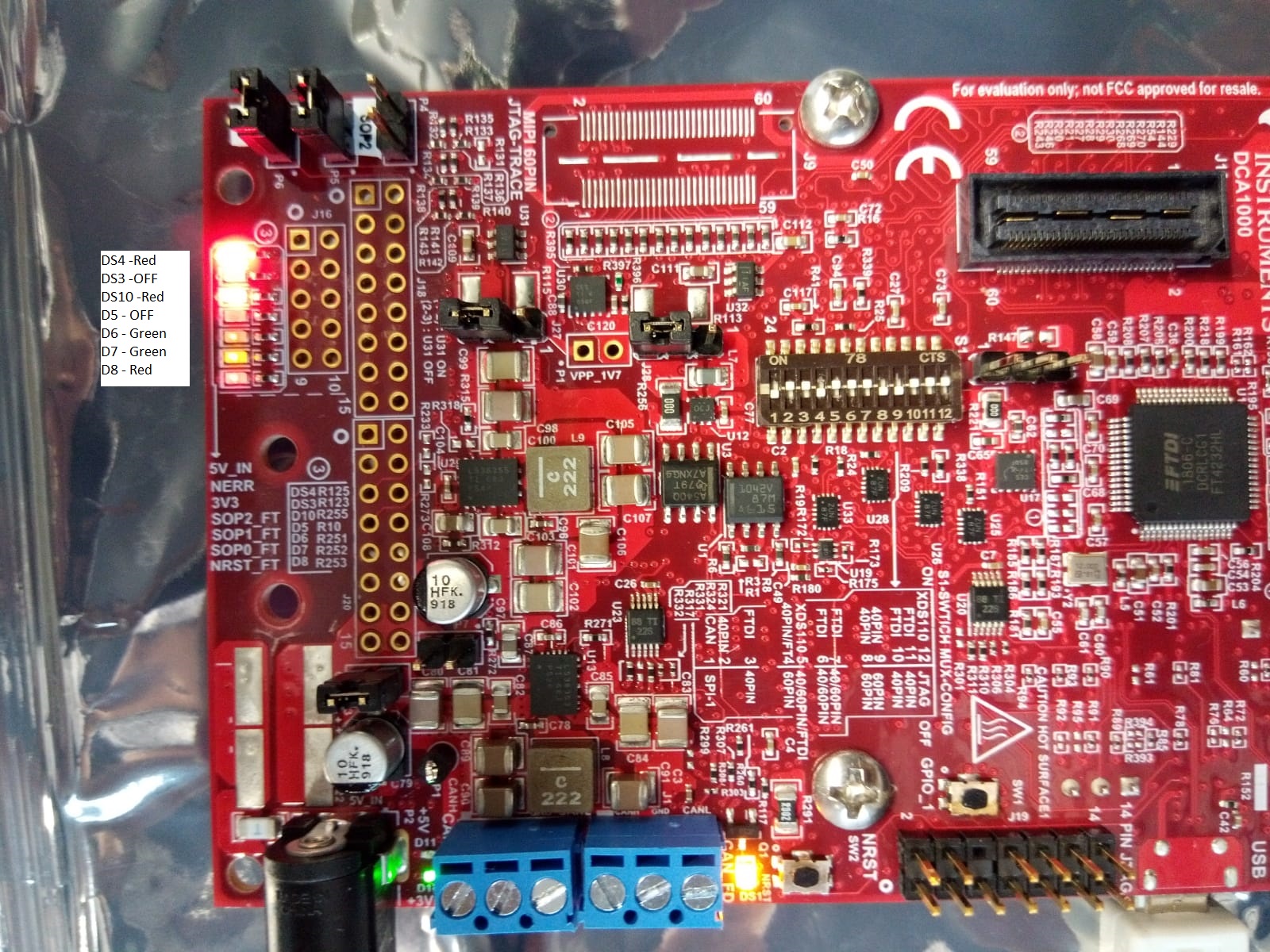
My system configuration is as follows. 

  1. Windows 10
  2. CCS 8.2.0.000007
  3. Target Platfrom IWR6843 + MMWAVEICBOOST Carrier Card

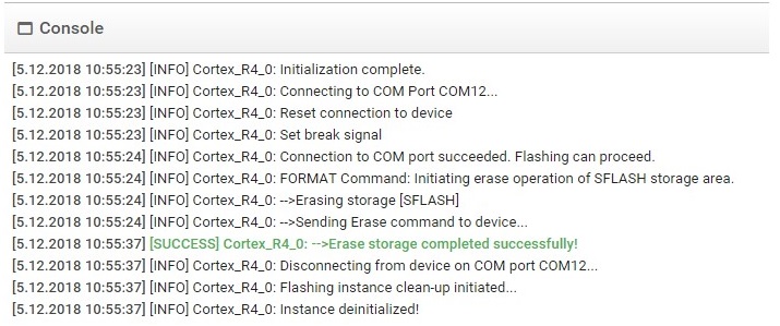
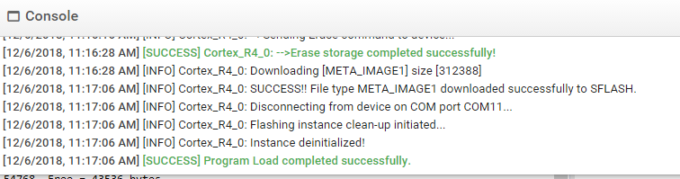
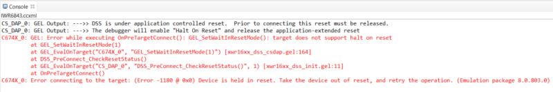
2. I tried running the PC_dss_68xx demo code on the target. While connecting the target, I'm getting the following error message.

Your support will be highly appreciated. 

Best Regards

Madhu K

  • Hi Madhu,

    In response to 2: You need to make sure you remove the jumper on SOP2. This is holding the device in reset and stopping you from connecting to it. If you still experience an issue after this, please make sure that you have flashed the device with the debug binary. This can be found at <sdk_install_dir>/packages/ti/utils/ccsdebug.

    I am still investigating the first issue.

    Regards,
    Justin
  • Hello Justin,

    Thank you for the reply.

    Jumber SOP2 is open on the EVM and I'm referencing the  swru546 document section 3.2.6.1 for this configuration. But one thing I noticed that the LED D8 is always glowing Red. Please see the LED indication in the below pic.

    Thanks

    Madhu K

  • Hi Madhu,

    From the picture above, there is a jumper on SOP0 and SOP1. For running demos or debugging with CCS, there should be a jumper on SOP0, and NO jumper on SOP1 or SOP2. So for SOP0 SOP1 SOP2 = 1 0 0. For flashing the device 1 0 1, for raw data capture with DCA1000 1 1 0.

    So for your use case, after flashing the device, ensure there is only one jumper on SOP0, and no jumpers on the other SOP pins.

    Regards,
    Justin
  • Hello Justin, 

    1. Yes, as you suggested I have tried that but still the same error is persisting. Moreover now DS3 LED also glowing RED. Also request you to clarify the jumper settings in the document swru546 Section 3.2.6.1. From this jumper settings, flash mode is clear and working fine. As per my understanding Development mode means Debugging and Functional mode means running a demo. Also differing with your description. Please correct me if I'm wrong. 

    2. Please have a look on the Uniflash console after flashing the binary. It is also observed that a different console print from the IWR1642 flashing.  

    3. Is there any update on DSP Project Creation for IWR6843.

    Best Regards

    Madhu K

  • Hi Madhu,

    You Uniflash output should show "[Success] Program Load completed successfully", as shown below:

    Follow this process to flash:

    1. Select the IWR6843 device.

    2. Set the COM Port to the value for UART Com Port.

    3. Select the IWR6843 debug binary from SDK 3 -> <SDK_Install_Dir>\packages\ti\utils\ccsdebug\xwr68xx_ccsdebug.bin

    4. Select load image.

    After the program is loaded successfully:

    1. Open CCS
    2. Open "Target Configurations"
    3. Select a IWR6843 configuration. If you do not have one, please create 1.
    4. Ensure you are using the XDS110 debug probe
    5. Ensure the device is in functional mode
    6. Connect to the device
    7. Load the Software to DSP and MSS
    8. Start running the software.

    Following these steps I am able to run in debug mode and connect to the device using the Matlab GUI.

    The jumper settings from the table are correct. To clarify:

    Flashing mode is for flashing.

    Development mode is for collecting raw data with DCA1000

    Functional mode is for running demos or debugging.  You need to use functional mode.

    Regards,

    Justin

  • Hello Justin,

    Thanks for your reply. As I mentioned in the initial post, I"m using the MMWAVEICBOOST Carrier Card with IWR6843 Antenna card. Are you using the same  setup? 

    If that is the case, my hardware should be the problem. Please look at my Uniflash console, it is not printing the "Binary downloading[META IMAGE]" message. Please confirm.

    Regards

    Madhu K

  • Hi Madhu,

    It appears that the issue is with the Uniflash procedure.  You are erasing the previous image, but not actually loading a new image. Please confirm that you are selecting the User UART port as shown below:

    I would select COM11 to flash the device.  Please see the People Counting User's guide and ensure the switches on the device are in the correct position.

    Regards,

    Justin

  • Hello Justin,

    Just to confirm you that I'm using the correct Port number and once again going to double check tomorrow and let you know that. In between are you using the Carrier Card with iwr6843 antenna plug-in module?

    Thanks
    Madhu K
  • Hi Madhu,

    I am testing with the ICB and ISK modules.

    Regards,
    Justin
  • Hello Justin,

    Issue-2 is  resolved, now I"m able to debug the example program, thank you for the support. 

    Do you have any update on the issue-1 (Creation of DSP Project for IWR6843 Target).

    Thanks

    Madhu K

  • Hi Madhu,

    Please import the project from TIREX.  If you have not downloaded TIREX, you can find it here.

    regards,

    Justin