This thread has been locked.

If you have a related question, please click the "Ask a related question" button in the top right corner. The newly created question will be automatically linked to this question.

IWR6843: Determining valid chirp parameters for SDK Demo

Part Number: IWR6843
Other Parts Discussed in Thread: MMWAVE-STUDIO, MMWAVE-SDK


We are attempting to characterize the IWR6843 for a short range application, maximizing angular velocity resolution, etc.

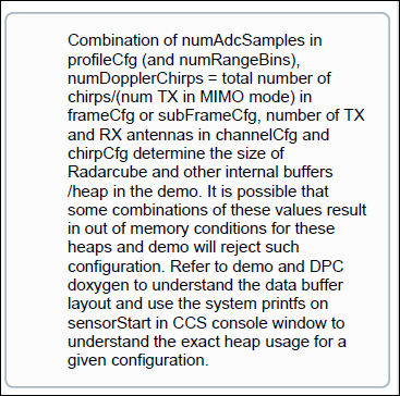
As we change some of the parameters, such as increasing the number of loops in frameCfg, the SDK firmware fails after a certain value.  We get some errors on the firmware debugger side that we haven't yet figured out (for example: Error: DPM Report 4 received with error:-40112 arg0:0x64 arg1:0x8004cd8).  Tracing the code, we find it is originating in the mmWaveLink level in rl_driver.c and rl_sensor.c.  We assume we are exceeding some constraint in the HWA and the mmWaveLink is rejecting the changed parameter.

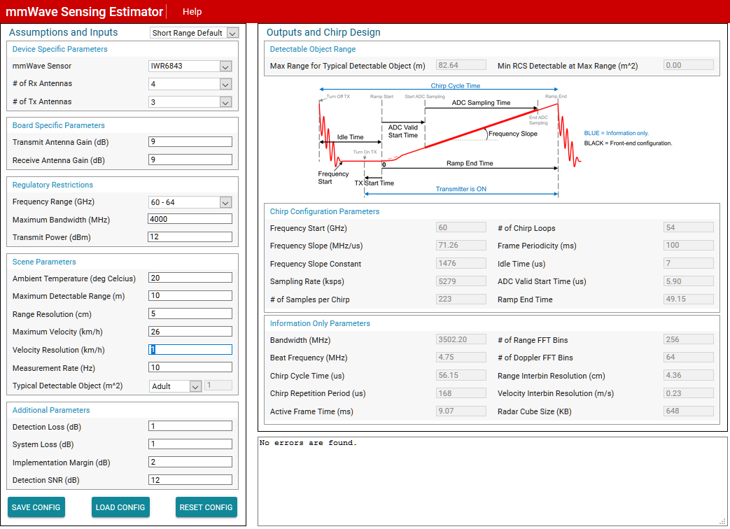
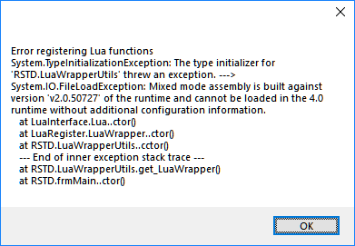
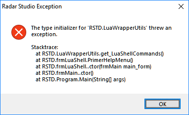
So hoping for a quicker path to our goal we decided to try the chirp timing parameter configuration calculator utility in Radar Studio.  But when we run Radar Studio the RadarAPI tab never appears.  We've installed multiple times, including all the related packages, MATLAB Runtime 8.5.1, National Instruments LabVIEW, MS C++ Runtime.  We got the "Script Failed" error shown in the mmWave Studio GUI User's Guide and installed the High Speed Data Converter Pro although we don't have the TSW1400 board described.  Next, an "error registering Lua functions".  But we aren't doing raw data capture and just need the calculator.  Our version says "mmWave Studio 2.0.0.2" and both the Help/About and the User's Guide have 2017 copyright dates.

Our goal is to determine chip parameters for the IWR6843, initially parameters that will be legal in the SDK 3.00.00.08 demo.  


• Is the Ramp Timing Calculator or Chirp Timing Parameter Configuration Calculator available anywhere other than Radar Studio?
• Are the calculations documented elsewhere?  I think in my searching I saw that they are not.
• With enough time we can figure out how our parameters are exceeding the HWA capacity, but is there a better way?
• Is the mmWave link code still beta?  It has a 0.9.1 version and still includes design and requirements IDs, reviewer comments and code inspection references.

Thanks

Dan Lewis

  • Hi,

    With regards to the MMWAVE-STUDIO installation errors, have you tried installing MMWAVE-STUDIO on a different machine? Also, make sure that you're installing Matlab 8.5.1 runtime 32 bit version as mentioned in the user guide.

    1. You can also use the mmWaveSensingEstimator which is a browser based tool that allows you to calculate the chirp parameters based on the application level requirements such as Max Range, Max Velocity, Velocity resolution, RCS etc.
    2. The internal calculations of the MMWAVE-STUDIO Ramp Timing Calculator are not exposed. However, the FMCW equations and Radar front-end constraints used by the Ramp timing calculator as well as the mmWaveSensingEstimator are mentioned in this app note:  Programming Chirp Parameters in TI Radar Devices.
    3. Please note that the mmwavelink and HWA are two separate entities. mmWaveLink is the interface with the Radar Front-End gets configured with the chirp configuration. A profile/chirp/frame configuration is valid from the front end perspective if it doesn't generate an mmWaveLink error. HWA or the Radar Hardware Accelerator on the other hand is the digital processing engine for processing the ADC data coming from the front-end. Please refer to the HWA user's guide for more details: http://www.ti.com/lit/pdf/swru526. You can also look at the Radar Accelerator Training Video for an overview.
    4. Note that we have not yet RTM'ed the 6843 device and the current 6843 silicon is engineering sample (ES1.0). The mmWaveLink code in the SDK is the interface towards the peer mmWaveLink which is part of the radarss firmware. The production radarss firmware as well as the mmWaveLink SDK code will be available with the production version of the 6843 device.

    Please mark this thread resolved if your question was answered.

    Regards

    -Nitin

  • Nitin --

    Thanks for the reply and we will try installing mmWave Studio on another machine.  We are familiar with both the mmWave Sensing Estimator and the app note.  

    Here's an example of our problem.  We want to develop a profile with (among other things) maximum radial velocity.

    1.  In the mmWave Sensing Estimator, select IWR6843 and Short Range Default.
    2.  Change Velocity Resolution to .5 km/h.  This gives an error message, "radar cube size is larger than available memory".
    3.  Change Velocity Resolution to  1.0 km/h.  No error message.
    4.  Enter the resulting parameters into the configuration file.  In this example, C:\ti\mmwave_sdk_03_00_00_08\packages\ti\demo\xwr68xx\mmw\profiles\profile_3d.cfg.  So:

    profileCfg 0 60 7 5.9 49.15 0 0 71.26 1 223 5279 0 0 30
    frameCfg 0 2 54 0 100 1 0
    etc.

    For startFreq, 60 GHz fails in the IWR6843 SDK Demo.  We find we must use 60.25.

    For adcStartTime, we find that 5.9, 5.0, 4.0, 3.75, 3.6 all fail.  3.0 and 3.5 work, no difference in the memory stats that the SDK Demo displays in the CCS debugger.

    For number of loops in the frameCfg, 32 gives a best radial velocity value (empirically, from reading COM prot data stream) of 0.8366 m/s.  Number of loops values of 40, 48, 56 and 60 all give radial velocity values of 0.4183 m/s.  A value of 64 loops fails with error -40112, DPM report 4.

    The way to find the performance limits and characterize the device have been trial and error. Using mmWave Sensing Estimator gives values that appear to be illegal when used in the SDK Demo.

    Next steps are to try getting the Radar API running -- maybe that will give different configuration values we can use -- and to start digging through the SDK code, to understand what is causing the errors we see with the values provided by the mmWave Sensing Estimator.  That's a lot of work while we are still just trying to evaluate the device suitability for our application.  Maybe you can bring some clarity to this and shorten our path.

    Dan Lewis

    Sensing estimator values:

    Example error from CCS.  Fails right after sensorStart command.

  • We set up a VM over the weekend and tried again to install mmWave Studio.  We successfully installed the mmwave_studio_02_00_00_02_win32 executable, the FTDI drivers, the MS C++ runtime, and the MatLab runtime.  Running the mmWave Studio executable as administrator, we get a "Error registering Lua functions" error + exception, see below. 

    Again, our reason for installing mmWave Studio is to gain access to the Radar API calculator, in the hope that it will provide useful configuration values for the mmWave SDK 3.00.00.08.  We don't need mmWave Studio for data acquisition, at least for now.

    Our goal is to be able to determine valid parameters for the .CFG file, which we cannot do with the sensing estimator. 

    Thanks
    Dan Lewis

  • Image was not attached to the last post, here it is:

  • Hi Dan,

    We have not tested MMWAVE-STUDIO on a VM. I would request you to install it on a native Windows machine along-with the required tools mentioned in the user guide for MMWAVE-STUDIO 2.0.0.2. You need to install only MMWAVE-STUDIO and the Matlab Runtime and additionally Visual C++ 2013 Redistributable if installing on Windows 10.

    Regards
    -Nitin
  • Thanks, Nitin. Doesn't seem like a VM issue but we will try installing mmWave Studio again on a Windows 10 machine. Meanwhile, I'll try restating our original question.

    Why does the mmWave Sensing Estimator give chirp parameters that cause the IWR6843 SDK Demo to halt with an error?

    Is there a tool that provides valid configuration parameters for chirp, frame, and profile for the IWR6843 SDK Demo?

    Thanks
    Dan Lewis
  • Hi Dan,

    Sorry for the delay. The mmWave Sensing Estimator generates values according to the RF front-end capabilities of the selected device i.e. what is possible with the device (while also generating information useful for designing the digital processing chain such as Radar cube memory, FFT size etc), while the mmWave SDK Demo has been tested with a sub-set of configurations. This means that not all configurations generated using the mmWave Sensing Estimator may work with the SDK demos. The SDK demos show only one possible processing chain and do not claim to be a processing chain which can process all possible use-cases. In other words, the configurations generated using the Sensing estimator are a Super-set of what is supported by the SDK demos.

    The MMWAVE-SDK 3.0.0.8 user guide also mentions this in the following note:

    Regards

    -Nitin