This thread has been locked.

If you have a related question, please click the "Ask a related question" button in the top right corner. The newly created question will be automatically linked to this question.

CCS/PGA460: Batch configuration parameters behave differently

Part Number: PGA460
Other Parts Discussed in Thread: , ENERGIA

Tool/software: Code Composer Studio

Hi,

After evaluating PGA460, we decided to make PCB to evaluate the operation status of multiple PGA460.However, after configuring them separately, we found that Echo Data Dump results of some chips were not what we expected.The peak value of the vibration attenuation is obviously smaller than the normal case.

The PCB includes the peripheral circuit of PGA460 and a TTL protocol to RS232 protocol conversion circuit.Use STM32 MCU UART drive it.The 12 v power supply.

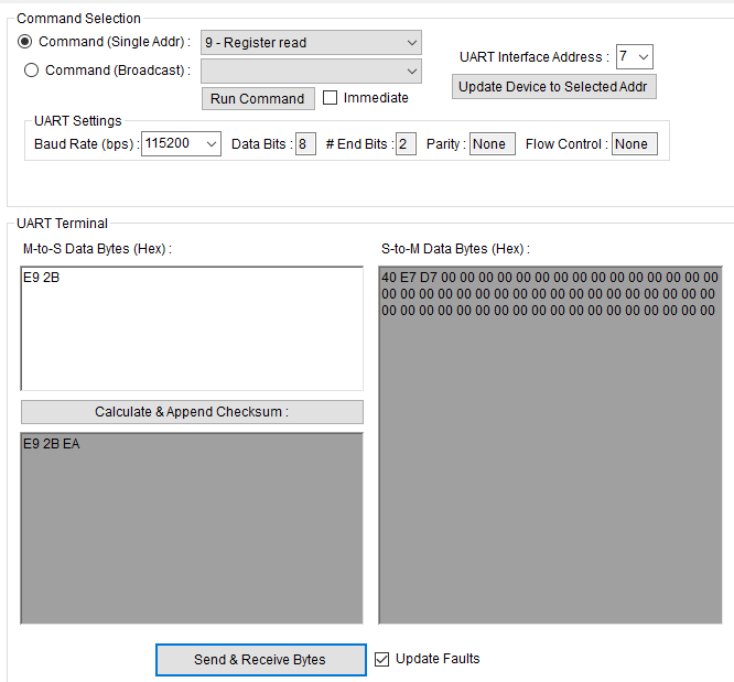
The following are the configuration parameters of PGA460.

From 15H to 2AH:{0xAF,0XFF,0XFF,0X2D,0X68,0X36,0X5C,0X8A, 0X0F,0X03,0X12,0X68,0X51,0X03,0X00,0XEE,0X7C,0X0A,0X00,0X00,0X08,0X00}

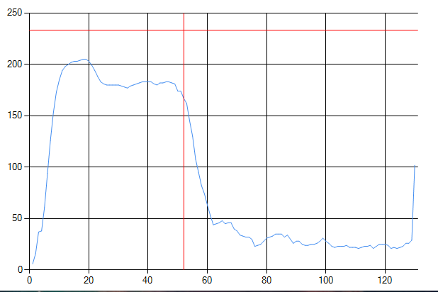
            Abnormal ECHO DATA DUMP DATA image(Use preset 1 for burst and listening)

                        The normal ECHO DATA DUMP DATA image(Use preset 1 for burst and listening)

We have tried switching between normal and abnormal modules, but the result is the same as before.And I tried to replace some components on the PCB, but there was still no result.

For this, can we try to use two different PGA460 devices to drive the same transducer?That is, use abnormal module to issue only listening instruction, use another normal module to issue burst and listening instruction, or vice versa (in the case of directly connecting the transducer pin on the corresponding PCB).

  • user5886154,

    Did you use the PGA460-Q1 EVM and GUI to initially evaluate the PGA460? If so, is the echo data dump performance consistent and match to what you have shown above?

    If I understand the error correctly, you are comparing the performance of two independent PGA460 modules, both of which have the same hardware and register configuration, but are returning different echo data dump performance results. As you suggested, have you tried swapping the transducers between the two modules to determine if it is the transducers that are at fault for the performance variation?
  • Thank you for your opinion. After the test, it can be confirmed that the phenomenon is caused by the transducer.We found that we could change the frequency of the transducer to get the result I wanted.Specifically, between 56khz and 59khz, transducers are activated one by one and echo data is collected until sufficient ideal waveform results are obtained.The ported autoThreshold function is then run, but the effect is not ideal within the preset range.I would like to ask if there is a more reliable solution.At the same time, how should I determine whether the object being detected is in the blind area of close range (0-25cm in our application) or outside the detection range (we set the value to 255cm)?

    In addition, when configuring the serial port id, it was found that when the id was 4-7, the data transferred from pga460 to MCU could not pass the verification.The sending and response of data fields and instructions are normal, only the returned data cannot pass the verification.Here is my check function:

    u8 Checksum(u8 *p,u8 len)
    {
     u16 sum=0;
     u8 i;
     for(i=0;i<len;i++){
      sum+=*p;
      if(sum>255){
       sum=((u8)sum)+1;
      }
      p++;
     }
     return ~((u8)sum);
    }

  • user5886154,

    If you know you have a unreliable/blind zone of sub-25cm, I recommend that you saturate your initial threshold level to prevent false-positives in this measurement range. See PGA460 FAQ#5.2 ( ) for details of saturating the threshold for a masking effect of ignoring echo data. Alternatively, you can set the number of objects to detect in your burst/listen command to be greater than one (up to eight) to check for false-positives in the blind zone, but also detect a real object at 255cm.

    For you checksum function, please refer to the following checksum function example implementation from the "PGA460 Energia Library and Code Example" software ( ):

    /*------------------------------------------------- calcChecksum -----
     |  Function calcChecksum
     |
     |  Purpose:  Calculates the UART checksum value based on the selected command and the user EERPOM values associated with the command
     |		This function is not applicable to TCI mode. 
     |
     |  Parameters:
     |		cmd (IN) -- the UART command for which the checksum should be calculated for
     |
     |  Returns: byte representation of calculated checksum value
     *-------------------------------------------------------------------*/
    byte pga460::calcChecksum(byte cmd)
    {
    	int checksumLoops = 0;
    	
    	cmd = cmd & 0x001F; // zero-mask command address of cmd to select correct switch-case statement
    	
    	switch(cmd)
    	{
    		case 0 : //P1BL
    		case 1 : //P2BL
    		case 2 : //P1LO
    		case 3 : //P2LO
    		case 17 : //BC_P1BL
    		case 18 : //BC_P2BL
    		case 19 : //BC_P1LO
    		case 20 : //BC_P2LO
    			ChecksumInput[0] = cmd;
    			ChecksumInput[1] = numObj;
    			checksumLoops = 2;
    		break;
    		case 4 : //TNLM
    		case 21 : //TNLM
    			ChecksumInput[0] = cmd;
    			ChecksumInput[1] = tempOrNoise;
    			checksumLoops = 2;
    		break;
    		case 5 : //UMR
    		case 6 : //TNLR
    		case 7 : //TEDD
    		case 8 : //SD
    		case 11 : //EEBR
    		case 13 : //TVGBR
    		case 15 : //THRBR
    			ChecksumInput[0] = cmd;
    			checksumLoops = 1;
    		break;
    		case 9 : //RR
    			ChecksumInput[0] = cmd;
    			ChecksumInput[1] = regAddr;
    			checksumLoops = 2;
    		break;
    		case 10 : //RW
    		case 22 : //BC_RW
    			ChecksumInput[0] = cmd;
    			ChecksumInput[1] = regAddr;
    			ChecksumInput[2] = regData;
    			checksumLoops = 3;
    		break;
    		case 14 : //TVGBW
    		case 24 : //BC_TVGBW
    			ChecksumInput[0] = cmd;
    			ChecksumInput[1] = TVGAIN0;
    			ChecksumInput[2] = TVGAIN1;
    			ChecksumInput[3] = TVGAIN2;
    			ChecksumInput[4] = TVGAIN3;
    			ChecksumInput[5] = TVGAIN4;
    			ChecksumInput[6] = TVGAIN5;
    			ChecksumInput[7] = TVGAIN6;
    			checksumLoops = 8;
    		break;
    		case 16 : //THRBW
    		case 25 : //BC_THRBW
    			ChecksumInput[0] = cmd;
    			ChecksumInput[1] = P1_THR_0;
    			ChecksumInput[2] = P1_THR_1;
    			ChecksumInput[3] = P1_THR_2;
    			ChecksumInput[4] = P1_THR_3;
    			ChecksumInput[5] = P1_THR_4;
    			ChecksumInput[6] = P1_THR_5;
    			ChecksumInput[7] = P1_THR_6;
    			ChecksumInput[8] = P1_THR_7;
    			ChecksumInput[9] = P1_THR_8;
    			ChecksumInput[10] = P1_THR_9;
    			ChecksumInput[11] = P1_THR_10;
    			ChecksumInput[12] = P1_THR_11;
    			ChecksumInput[13] = P1_THR_12;
    			ChecksumInput[14] = P1_THR_13;
    			ChecksumInput[15] = P1_THR_14;
    			ChecksumInput[16] = P1_THR_15;
    			ChecksumInput[17] = P2_THR_0;
    			ChecksumInput[18] = P2_THR_1;
    			ChecksumInput[19] = P2_THR_2;
    			ChecksumInput[20] = P2_THR_3;
    			ChecksumInput[21] = P2_THR_4;
    			ChecksumInput[22] = P2_THR_5;
    			ChecksumInput[23] = P2_THR_6;
    			ChecksumInput[24] = P2_THR_7;
    			ChecksumInput[25] = P2_THR_8;
    			ChecksumInput[26] = P2_THR_9;
    			ChecksumInput[27] = P2_THR_10;
    			ChecksumInput[28] = P2_THR_11;
    			ChecksumInput[29] = P2_THR_12;
    			ChecksumInput[30] = P2_THR_13;
    			ChecksumInput[31] = P2_THR_14;
    			ChecksumInput[32] = P2_THR_15;
    			checksumLoops = 33;
    		break;
    		case 12 : //EEBW
    		case 23 : //BC_EEBW
    			ChecksumInput[0] = cmd;
    			ChecksumInput[1] = USER_DATA1;
    			ChecksumInput[2] = USER_DATA2;
    			ChecksumInput[3] = USER_DATA3;
    			ChecksumInput[4] = USER_DATA4;
    			ChecksumInput[5] = USER_DATA5;
    			ChecksumInput[6] = USER_DATA6;
    			ChecksumInput[7] = USER_DATA7;
    			ChecksumInput[8] = USER_DATA8;
    			ChecksumInput[9] = USER_DATA9;
    			ChecksumInput[10] = USER_DATA10;
    			ChecksumInput[11] = USER_DATA11;
    			ChecksumInput[12] = USER_DATA12;
    			ChecksumInput[13] = USER_DATA13;
    			ChecksumInput[14] = USER_DATA14;
    			ChecksumInput[15] = USER_DATA15;
    			ChecksumInput[16] = USER_DATA16;
    			ChecksumInput[17] = USER_DATA17;
    			ChecksumInput[18] = USER_DATA18;
    			ChecksumInput[19] = USER_DATA19;
    			ChecksumInput[20] = USER_DATA20;
    			ChecksumInput[21] = TVGAIN0;
    			ChecksumInput[22] = TVGAIN1;
    			ChecksumInput[23] = TVGAIN2;
    			ChecksumInput[24] = TVGAIN3;
    			ChecksumInput[25] = TVGAIN4;
    			ChecksumInput[26] = TVGAIN5;
    			ChecksumInput[27] = TVGAIN6;
    			ChecksumInput[28] = INIT_GAIN;
    			ChecksumInput[29] = FREQUENCY;
    			ChecksumInput[30] = DEADTIME;
    			ChecksumInput[31] = PULSE_P1;
    			ChecksumInput[32] = PULSE_P2;
    			ChecksumInput[33] = CURR_LIM_P1;
    			ChecksumInput[34] = CURR_LIM_P2;
    			ChecksumInput[35] = REC_LENGTH;
    			ChecksumInput[36] = FREQ_DIAG;
    			ChecksumInput[37] = SAT_FDIAG_TH;
    			ChecksumInput[38] = FVOLT_DEC;
    			ChecksumInput[39] = DECPL_TEMP;
    			ChecksumInput[40] = DSP_SCALE;
    			ChecksumInput[41] = TEMP_TRIM;
    			ChecksumInput[42] = P1_GAIN_CTRL;
    			ChecksumInput[43] = P2_GAIN_CTRL;
    			checksumLoops = 44;
    		break;
    		default: break;
    	}
    
    	if (ChecksumInput[0]<17) //only re-append command address for non-broadcast commands.
    	{
    		ChecksumInput[0] = ChecksumInput[0] + (uartAddr << 5);
    	}
    	
    	uint16_t carry = 0;
    
    	for (int i = 0; i < checksumLoops; i++)
    	{
    		if ((ChecksumInput[i] + carry) < carry)
    		{
    			carry = carry + ChecksumInput[i] + 1;
    		}
    		else
    		{
    			carry = carry + ChecksumInput[i];
    		}
    
    		if (carry > 0xFF)
    		{
    		  carry = carry - 255;
    		}
    	}
    	
    	carry = (~carry & 0x00FF);
    	return carry;
    }

  • Thank you for your reply.But I think you may have misunderstood the problem I described.The problem with checksum is not that it has any problem with uart instruction, but that the data returned by PGA460 after running cannot pass the corresponding checksum.However, this phenomenon only occurs on devices with uart address set to 4-7, and will not occur on devices set to 0-3.This phenomenon makes it impossible for me to tell whether the problem is from my function or from PGA460.

    In the checksum function above.U8 is of type uchar, *p is the first address of the receive cache, and len is the length of data in the receive cache.

  • user5886154,

    Can you please provide an example of the return data + erroneous_checksum returned by the UART_ADDR=4-7 device which does no match your calculated return checksum? I've checked a few examples using the PGA460-Q1 EVM/GUI, and cannot replicate this error. Example: UART_ADDR = b111 (0x7) performing a register read of address 0x2B. PGA460 returns 0x{40 E7 D7}, where:

    • diagnostic field = 0x40
    • data at address = 0xE7
    • device calculated checksum = 0xD7

    Passing byte array 0x{40 E7} into the checksum calculator returns matching value of 0xD7.

    Executing register read command Verifying device generated checksum
  • Thank you for your reply. I have been on a business trip for some time, but I failed to reply in time. I hope you can understand.

    With this problem, I only found it in the returned echo datagram.

    As shown below:

    {40 51 B5 EE FC BC C3 EE FF FF FF FB F8 FF FF E7 78 B7 E1 F6 F7 E7 A9 6A 3F 23 2F 3E 41 3D 28 15 17 17 14 0B 0D 0F 0C 10 18 18 17 0C 12 16 16 14 0B 07 07 07 0D 11 16 16 14 0D 13 17 19 19 15 0F 0A 09 07 08 11 14 13 15 23 30 44 59 63 62 52 33 1D 18 17 1A 1D 1F 1F 1F 19 12 19 1A 19 15 13 14 14 16 15 15 11 0A 09 07 07 08 08 0A 0A 0C 0E 0E 0E 0D 0B 09 08 07 08 07 0A 0A 08 09 0C 0C 11 19 24 15 }

    In the case of my checksum function, the checksum would be 0XD4.But we receive 0X15, at which point uart_addr is 6.

    The problem cannot be identified because the GUI cannot support this validation.

  • user5886154,

    For the echo data dump return, the UART_ADDR should not impact the checksum since this is a slave return, and not a master issue.

    When you exclude the first byte (0x40), from the checksum calculation, the checksum result will be 0x15.
    If you calculate the checksum for the entire string as you have shown, the checksum result will be 0xD4.

    In the case of command 7 (read XDCR EDD), the device is calculating the checksum of the 128 echo data dump bytes, and excluding the first diagnostic field value.
  • Through your reply, I think I have found a solution to this problem.We only need to determine how to validate the return value based on its address segment.However, the scheme needs to be further tested for reliability.

    Besides, if possible, I hope to know the reason for this phenomenon.Thank you very much.