This thread has been locked.

If you have a related question, please click the "Ask a related question" button in the top right corner. The newly created question will be automatically linked to this question.

IWR1642BOOST: GPIO pins on J5 and J6

Part Number: IWR1642BOOST
Other Parts Discussed in Thread: IWR1642

Hi, I need to get 3 GPIO output and 1 GPIO input from the J6 nd J5 connector of the iwr1642 IC.

But I have GPIO 0,1,2. but during the insertion of 0Ohm resisistor the pad is been damaged.I have already used GPIO1 for onw output. GPIO 2 is been used for one input.

how do I get the rest of 2 signlas. when I went through datasheet it gives some adress for each ball. Is it possible to use any of the 2 pins in J5 or J6 connector of IWR1642 IC?

pls help me for this.

  • Hi,

    Table 4.6 of the IWR1642 shows the list of pin and the multiplexing options. As shown on the table there a few other pins that can be muxed as GPIO.

    • You will need to check the schmatic for the IWR1642BOOST to determine which pins on J1,J2 can be muxed as a GPIO
    • Determine which of the pin can be used for your application, since you might lose some other peripheral
    • Make SW modifications to mux GPIOs to the selected pins 

    Regards,

    Charles O

  • Hi, As you tolds I went through the doc and I found below points and ref images,

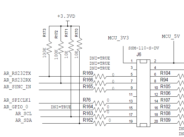
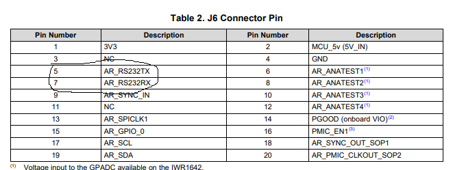
    J6 has AR_RS232RX AND TX 2 PINS WHICH CAN BE CONFIGURED AS GPIO 15AND 14. AND ADRESS ALSO GIVEN BUT WHERE DO WE PUT THIS ADRESS. COULD YOU PLS GIVE ONE EXAMPLE