


Other Parts Discussed in Thread: AWR1642, AWR1243
Tool/software: TI-RTOS
Hello, I am having some trouble reading in raw data via ethernet from the DCA1000EVM. According to the DCA1000 User Guide, the data format is as follows:
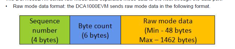
I have SW4 on the DCA1000 DIP switch set to Raw Data, so this is the type of packet I am receiving. The specific configuration of the radar device was for 4 receivers, complex 1x data, 256 ADC samples per chirp. After I received a packet, the length of every packet was 1466 bytes: 4 for the sequence number, 6 for the byte count, 1456 for the data. This means there are 1456/2=728 IQ samples and 728/2=364 ADC Samples in the packet. I know that each sample is LSB so I would reorder the following stream like so:
abfc9afc79fe61fc29fe590115fa7df933032c0517fa02fb41072708f5fc8fff (RAW)
fcbafc9afe79fc61fe290159fa15f97d0333052cfa17fb0207410827fc5fff8f (REORDER)
Where red is RX1, green is RX2, blue is RX3, and black is RX4. Next, I would take each I and Q sample individually, convert it to hex, and subtract 2^15 to convert out of 2's complement notation. I take the I and Q sample for each receiver and combine it into one complex sample by the following: I+1j*Q. Therefore, after capturing 3 packets (3 packets * 1456 bytes/packet = 4368 bytes > 4096 bytes needed for 256 complex samples for 4 receivers) a full chirp's worth of information is captured and ready for a 1D fft. I apply the fft across each receiver so that I am taking the fft of an array of size 256 four separate times. I take the absolute value of the fft and then plot it on a log scale.
Here are my questions:
1) Do I need to have the DCA1000 DIP SW3 set to AWR1642 or AWR1243 mode? I am using the AWR1642, but if I want a high ADC data rate out of my board, would using AWR1243 mode affect the parsing of the raw data capture?
2) Does the ADC data pick up where it left off while transitioning between packets? For example, if the last data sample at the end of packet 1 is RX0 (I) would the first data sample at the beginning of packet 2 be RX0 (Q)?
3) Do you notice anything wrong with my procedure of taking the 1D FFT?
For some reason, I have not been able to reproduce the results that I see in the demo visualizer or mmWave Studio and I am confused because I thought followed the ADC raw data capture guide and the DCA1000 user guide perfectly.

