This thread has been locked.

If you have a related question, please click the "Ask a related question" button in the top right corner. The newly created question will be automatically linked to this question.

AWR1642BOOST: Selecting between the on board antennas

Part Number: AWR1642BOOST
Other Parts Discussed in Thread: AWR1642

Hello,

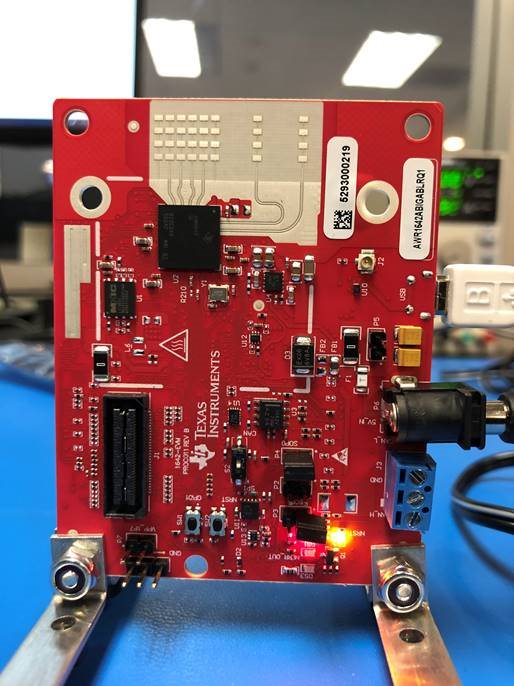
I have a few quick questions, can you comment on 1-5 below? In reference to the below picture:

1. Out of the 2 TX antennas, if I choose 1 in the param file, am I selecting the one to the very far right in the board or the other one?

2. If I choose 2, then I guess it’s the other one, and if I choose 3, then it’s both, correct?

3. When it’s both, we are not sure we understand the sequence with which the card operates. Is it one chirp from 1 TX and 1 chirp from the other? Is it one chirp from both at the same time?

4. On the RX side, we can choose, 1, 2, 4, 8, 15, which selects the first, the second, the third, the forth or all of them together respectively. But, again, which is which? In other words, which one is the 1st and which one is the 4th in the photo?

5. Also, about the RX, if we choose 15, and all are receiving, how does it work, you get one chirp back from one at the time, all at the same time….what is it?

  • Hi Ryan,

    1. The antenna to the far right is TX2 and the other one is TX1. If you choose 1 in the chirpCfg command in the config file, you would activate TX1.

    2. If you choose 2, you would activate TX2, and if you choose 3 you would activate both.

    3. Each frame consists of a sequence of chirps. The chirps are individually configured using the chirpCfg command in the config file. Each chirp can activate a different TX or combination of TXs. The chirps are run in numerical sequence.

    If you call the chirpCfg command with both TXs enabled (value of 3), then it is one chirp with both TXs simultaneously on.

    4. RX1 is to the left in your photo and RX2 is to the right. Note that we have two dummy antennas on either end of the RX antenna array.
    (Please refer to the AWR1642 datasheet for the pinout for this part; the schematic and layout for this board are available here and contain this information (www.ti.com/.../AWR1642BOOST) ).

    5. If multiple RXs are enabled, they all work in parallel. There are individual ADC and sampling chains for each RX and you get 4 sets of raw ADC data, one per RX. The reflected signal from each chirp is captured by all 4 RXs, and depending on the separation between each antenna, the reflected signal from a single object travels a slightly different path to each antenna resulting in a phase shift. This information is useful to detect the angle of arrival.

    Please refer to the following training series that explains this:
    training.ti.com/mmwave-training-series

    Module 5 covers angle estimation using multiple RXs.

    Best Regards,
    Anand