This thread has been locked.

If you have a related question, please click the "Ask a related question" button in the top right corner. The newly created question will be automatically linked to this question.

TDC7201: The random error is too large and the waiting time for INTBx going back to high is too long

Part Number: TDC7201

Hi Team/Expert,

I've written a fpga code for tdc7201, using combined operation with each TDCx working in measurement mode 1, while the frequency of external reference clock is 8MHz (Stability < +/-30ppm) and the frequency of SCLK is 15MHz generated by fpga.

Using fpga itself as the start-stop generator, I've taken some simulation tests to tdc7201 range from 100ns to 2us. It seems that every process goes right, but the result is not as good as expected.

First the random error (peak-to-peak) is always 1.4ns ~ 2.5ns, which means 0.2m~0.4m distance error for LIDAR.  Test result for 100ns is shown below as an instance, where the measurement runs for 50 times.


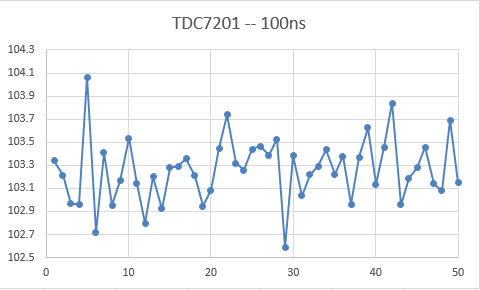
Since the standard deviation of tdc7201 is supposed to be 35ps, the measured random error (peak-to-peak) should not be so large I think, but I have no idea what's wrong here.

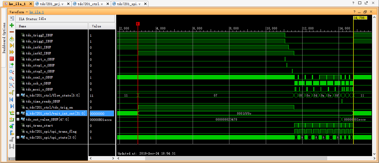
Second is that every time I clear the TDCx_INT_STATUS register bit NEW_MEAS_INT by writing a 1 to it through SPI, it takes me as long as 8.73ms to wait for both INTBx going back to high.

As is shown in the waveform below, I’ve built a counter named “wait_int_cnt” to measure this time and a large number 0x1ff0c was obtained, which means 8.73ms at 15MHz clock, while my program have done nothing but wait for both INTBx going back to high during this period.

It's another serious problem that because of such a long waiting time, the measurement rate of LIDAR is limited to less than 110Hz.

Is this waiting time of 8.73ms normal? Is there any checking or improvement advice?

Thanks a lot for your great support on this!

Best regards and happy new year,

Mark Lewis

  • Hi User,
    We've got your request. Our response may be delayed due to holiday season, we will get back to you as soon as possible.

    Best Regards,
    Bala Ravi
  • I see. It does not matter.

    Enjoy your holiday and Happy New Year.

    Best Regards,

    Mark Lewis

  • Mark,

    Please send me the register setting for the condition that your running the device at.
  • Hi Bharat,

    Here is my state machine flow with register settings.

    (1) Initiate.

    (2) Wait for 3ms.

    (3) Write 0x00 to TDC1_CONFIG2 and TDC2_CONFIG2 at the same time.

    (4) Write 0x07 to TDC1_INT_MASK and TDC2_INT_MASK at the same time.

    (5) Write 0x1F to TDC1_INT_STATUS and TDC2_INT_STATUS at the same time.

    (6) Wirte 0x41 to TDC1_CONFIG1 and TDC2_CONFIG1 at the same time.

    (7) if "( tdc_intb1 & tdc_intb2 ) == 1", go to (8); else wait.

    (8) if "( tdc_trigg1 == 1) & (tdc_trigg2 == 1) ", go to (9); else wait.

    (9) if " (tdc_intb1 == 0) & (tdc_intb2 == 0) ", go to (10); else wait.

    (10) Write 0x00 to TDC1_INT_MASK and TDC2_INT_MASK at the same time.

    (11) Read TDC1_TIME1.

    (12) Read TDC1_CALIBRATION1.

    (13) Read TDC1_CALIBRATION2.

    (14) Read TDC2_TIME1.

    (15) Read TDC2_CALIBRATION1.

    (16) Read TDC2_CALIBRATION2, and then return to (4) to begin the next loop.

    In my application, there is no need to read out TDCx_CLOCK_COUNT.

    Wish for your advice~

    Mark

  • Mark,

    I do not see anything in your setup that could improve your accuracy. Please note that any inaccuracy in clock signals can change the measured value. Refer section 8.3 in the datasheet. Also you have provided me with read points wherein the average looks close to 103.4ns and please check the standard deviation for this spread.