This thread has been locked.

If you have a related question, please click the "Ask a related question" button in the top right corner. The newly created question will be automatically linked to this question.

AWR1243BOOST: LDO Bypass with ES3.0

Part Number: AWR1243BOOST
Other Parts Discussed in Thread: DCA1000EVM, , AWR1243
I am using an ES3.0 AWR1243BOOST with a DCA1000EVM and mmWave Studio 2.0.0.2.
System setup and data acquisition are working properly.
The RevB version of AWR1243BOOST with ES3.0 has a PMIC that provides 1.0 V to VIN_13RF1 and VIN_13RF2.
It also has those AWR1243 inputs directly connected to the AWR1243 VOUT_PA pin.
I assume this is to support simultaneous 3 TX operation, as described in the AWR1243 data sheet, page 15.
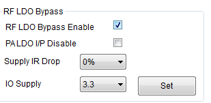
The mmWave Studio User's Guide, page 24, says the RF LDO Bypass Enable and PA LDO I/P Disable check boxes should not be checked, whereas the AWR1243 ICD, version 0.98, page 133,
says: "VIN 13RF2 is shorted to VOUT PA on the board and the PA LDO should be disabled"
Question 1:
What are the proper RF LDO Bypass Enable and PA LDO I/P Disable settings in the
StaticConfig tab in mmWave Studio 2.0.0.2 for AWR1243BOOST ES3.0?
Question 2:
The AWR1243BOOST, Rev B with ES3.0 meets the simultaneous 3 TX requirements listed in the AWR1243 data sheet.
Does the AWR1243BOOST, Rev B with ES3.0 support simultaneous 3 TX operation?
Thank you,
mmUser
  • Hi mmUser,

    The AWR1243BOOST Rev B does not by itself support simultaneous 3 TX operation.

    Simultaneous 3 TX operation is only supported in the AWR1243P - an EVM for this part is not currently available, but it is a drop-in replacement to the AWR1243 ES3.0 part on the AWR1243BOOST Rev B EVM.

    For proper operation of the Rev B board, you need to select the "RF LDO Bypass Enable" option as in the following screenshot.

    Best Regards,

    Anand

  • Hi Anand,

    Thank you for your quick reply.

    Regarding the LDO settings, your suggestion doesn't seem to match the ICD, page 133. For the Rev B AWR1243BOOST, the schematics show that VIN_13RF1, VIN_13RF2, and VOUT_PA are all connected to the PMIC 1.0 V output. That matches the third USECASE in Table 5.63 suggesting that both LDO boxes should be checked. Please let me know if I'm interpreting that incorrectly.

    Regarding 3 TX operation, is TI planning to offer an AWR1243BOOST with the AWR1243p? If so, do you know the proposed schedule?

    Thank you,

    mmUser

  • See follow up description
  • Hi mmUser,

    You're correct - The PA LDO I/P disable also has to be selected for the Rev B boards.

    Best Regards,
    Anand