This thread has been locked.

If you have a related question, please click the "Ask a related question" button in the top right corner. The newly created question will be automatically linked to this question.

PGA411Q1EVM: Angle Tracking Loop Configuration and Influence

Part Number: PGA411Q1EVM

Hi there!

we are using the PGA411-Q1 EVM Evaluation Board with the encoder emulator output and do have a couple of questions.

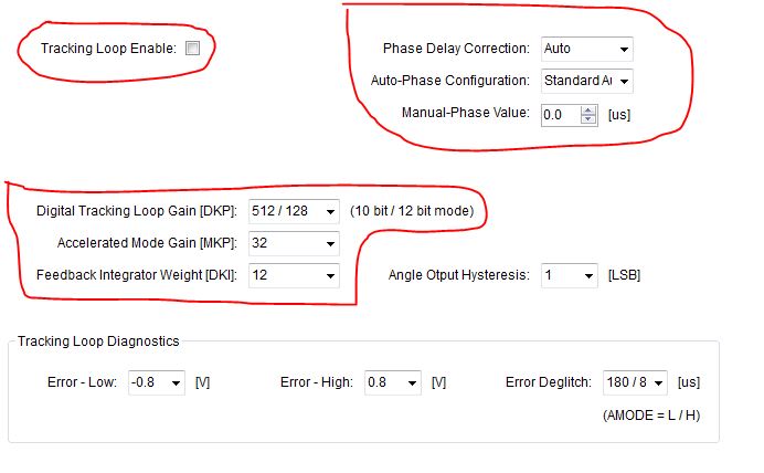
We are wondering about the settings of the Tracking Loop: If the tracking loop is disabled, the parameters (e.g. DKP) do still have an influence on the angular output quality. Why is that the case? Further, we would like to ask, what is the numerical meaning of the parameters DKP, MKP and DK (normally these are the control parameters), hence the numerical base is always two? Concerning the Phase Delay Correction, why is it always necesarry to be active and what is it good for? Is it related to the tracking loop?

Background information: we are planning to gauge a resolver type without an active tracking loop.

Thank you very much for your help so far!

Best regards,

Chris

  • Hi Christoph,
    We've got your request. Our expert with this device is out of office. We will get back to your next week.

    Best Regards,
    Bala Ravi
  • Christoph,

    The tracking loop parameters will have no impact if the tracking loop is disabled. Please note that the PGA411 will not output an angle if the tracking loop is turned off. I do not know of an application where you would permanently keep the tracking loop off.

    DKI is the integrator scalar, DKP is the proportional scalar, and MKP is a multiplier to DKP when the tracking loop error is large. Adjusting DKI and DKP will affect the dynamic response of the system. The typical values are almost always used for these parameters.

    In a typical resolver system, the resolver sensor and AFE filtering will introduce a delay between the excitation signal and modulated SIN/COS signals. To extract the angle information, the PGA411 demodulates the SIN/COS signals, but to demodulate correctly, the phase delay must be known. Without phase delay correction, the tracking loop can take longer to lock and it is possible for error. Manual phase delay mode is also fine if you want tighter control over your system.
  • Hello Clancy,

    first of all I would like to thank you very much for your professional answer. We now understand the behaviour of the Angle Tracking Observer a bit better. Though we have some more detailed questions about the topic as written below:

    For a better understanding here a few details about our project: In our case, we want to evaluate the performance of a resolver by comparing its angle with another (reference) sensor on a test bench. Your PGA board should help us by providing the electrical or mechanical angle of the resolver itself. The two angular informations will be compared with each other using a data acquisition card with two counter inputs. The reference sensor is connected to one of those counter inputs(e.g. CNT0). Your PGA board is conected to the other counter input (CNT1) by using the encoder output (OUT A,B and Z). That works very good to compare the angular information.

    Considering the tracking loop parameters having no impact when the loop is disabled: When turning off the loop (checkbox @ "Tracking Loop Enable"), we still do get a angular information at our encoder output (nothing changes). The idea resp. application for turning it off would be to evaluate the resolver without a tracking loop only. Hence we have read in your Data Sheet, it would be better leving the tracking loop on because of phase correction etc. --> Our questiion (#1): What is the reason for this checkbox and what exactly is turned off when disabling it? Which module in Figure 17 in the Data Sheet is being disabled?

    Regarding DKP, MKP and DKI, we know have figured out the influence (thank you for that). In our test cases we just have static speed (no dynamic analysis) and our angular information is always stable. --> Our question (#2) :What we don't know is, what are the typical values or let's say the IDEAL values for a certain resolver, hence we have not found any formular in your Manuals. We figured out that by varying the settings emperically, they do not have a big influence (especially MKP & DKI) on the angle. Only DKP is responsible for a larger or smaller angle error. We also wonder, if the parameters have an influence on the rotational speed (e.g. from 1krpm --> to 10krpm . We figured out that the angular error is depending on the settings of DKP. This is why we want to know the ideal one. When we talk about the settings: In a normal (e.g. 3rd order tracking loop) there are numerical parameters to set. At your application it's only possible to set 2^n numerical values. Can we transfer that in some way?

    The typical resolver system evaluation is clear for us. Our question in this case would only regard the settings of your Phase delay correction: --> Our question (#3): Is it fine by leaving the Phase Delay Correction at "Auto" and the Auto-Phase Configuration to "Short Fault Detection Threashoulds" when we do not know the phase delay? We do not want to control it via another system.

    -> Our question (#4): Because, as you said right, the resolver signals will be demodulated: Is it possible to readout the demodulated resolver feedback signals in an analog form (e.g. from a DAC) somewhere at the board ? (Data Sheet Fig. 16: sin(phi), cos(phi).


    I know, that we have got a lot of questions but you would help us very much by answering them, so we can understand the behaviour better and can continue some research.

    Note: The Data Sheet we use is the following version: SLASE76E –NOVEMBER 2015–REVISED AUGUST 2017.

    Best regards and thank you for your effort of answering our questions,

    Chris

  • 1.) All of that figure is disabled. The OUTA/B/Z are direct outputs of the angle output, so you should not see them increment when the digital tracking loop is off. If the resolver's angle is changed, you should not see that change on OUTA/B/Z.

    2.) Most of our testing has been done with DKI = 4, and DKP = 4. If you adjust these values, the bandwidth will also be adjusted, which can have an impact at higher speeds. Unfortunately, all of the information about DKI and DKP is already in the datasheet. We do not have additional information to share.

    3.) Absolutely!

    4.) That is not possible.