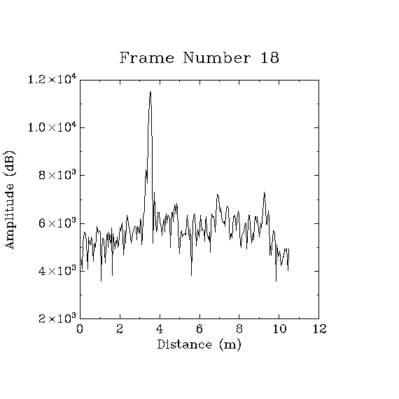
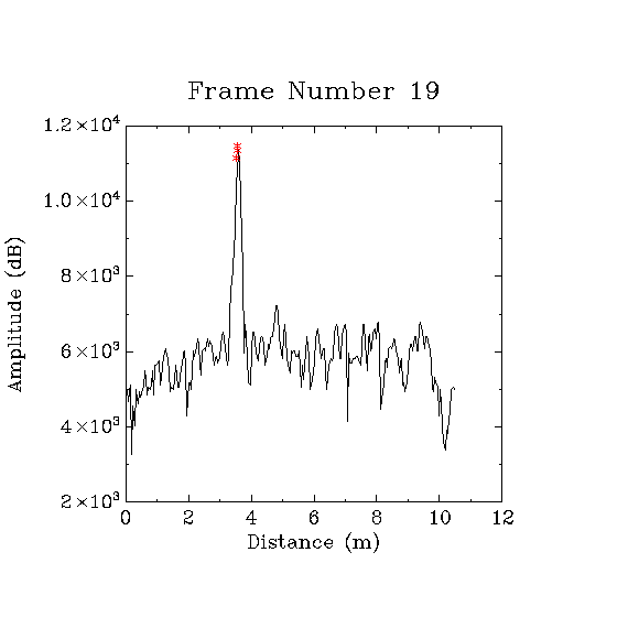
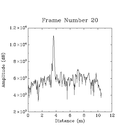
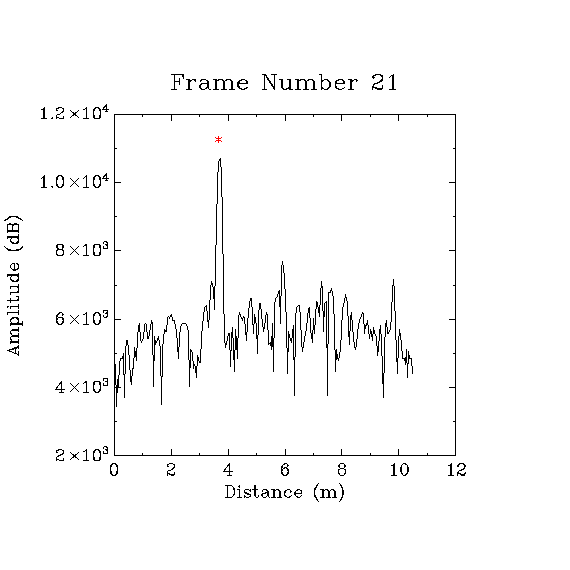
This thread has been locked.

If you have a related question, please click the "Ask a related question" button in the top right corner. The newly created question will be automatically linked to this question.

IWR1443: Velocity acquisition

Part Number: IWR1443
Other Parts Discussed in Thread: MMWAVE-STUDIO

Hi,

I have a few questions concerning velocity acquisition.

1.  It appears that velocity information is only available from the objOut structure.  It appears that this structure is populated by the following sequence of functions:

MmwDemo_dataPathWait1D(dataPathObj)

MmwDemo_process2D(dataPathObj)

MmwDemo_processCfar(dataPathObj, &numDetectedObjects)

MmwDemo_processAngle(dataPathObj)

Correct?  It appears that there is no other alternate (convenient) approach to obtain velocity information for a detected object.  Correct?

2.  Attached are some images where rangeDopplerLogMagMatrix (dopIdx=0) data is plotted along with the peakVal and rangeIdx data from the objOut structure.  Even though the downrange profile appears to have a single peak, several detected objects appear for the same single (?) peak and their peak values can be sufficiently different from the down range profile values.  I have reviewed the documentation in the doxygen directory and I am still fuzzy.  Can you please provide additional guidance on why the multiple peaks and peak values in the objOut structure appear to be inconsistent from the  rangeDopplerLogMagMatrix data?  In some cases, a frame may have no detected objects but clearly, there should be.  If I lower the threshold value, more detected objects are found (as expected) and their peak values have a greater variation in peak value.

3. The cfarCgf and peakGrouping parameters control what I observe in the above block.  I have used these parameters

cfarCfg 0 2 8 4 3 0 5120
peakGrouping 1 1 1 1 229

Choosing alternate parameter values to correlate the data in rangeDopplerLogMagMatrix and objOut appears to be elusive.  Can you please provide any guidance for this?

I guess what I am looking for is a single peak value and corresponding velocity for each peak in a rangeDopplerLogMagMatrix profile.

Thank you.

Al

  • Hi Allen,

    1. It appears that there is no other alternate (convenient) approach to obtain velocity information for a detected object.  Correct?

    [NS]: You need to run the Radar processing chain which includes Range FFT, Doppler FFT, and CFAR Detection before you can get the velocity for the objects which cross the detection threshold and then run the Angle of Arrival. The result of the above functions is the detectedObject list which has the velocity of each object.

    2. Even though the downrange profile appears to have a single peak, several detected objects appear for the same single (?) peak and their peak values can be sufficiently different from the down range profile values

    [NS]: You haven't provided your scene information. But there can be multiple objects with the same range bin because of

    a) Multi-object beam-forming is enabled which outputs the second highest peak in the same range bin if it's at a different azimuth angle and

    b) If the objects enough difference in velocity to be separated by the configured Doppler resolution.

    Can you please provide additional guidance on why the multiple peaks and peak values in the objOut structure appear to be inconsistent from the  rangeDopplerLogMagMatrix data?  In some cases, a frame may have no detected objects but clearly, there should be.

    [NS]: Please run the demo with the mmWaveDemoVisualizer and then see if you see the above issues. You can save the UART data coming over the COM port and analyze it as well.

    I guess what I am looking for is a single peak value and corresponding velocity for each peak in a rangeDopplerLogMagMatrix profile.

    The values in the Range Doppler Log Matrix may not correspond one to one to the detected object list as more processing which includes CFAR, PeakGrouping and Angle of Arrival calculation is performed on those before the final detected object list is formed.

    -Nitin

  • Hi Nitin,

    Thanks for the feedback and conformation.  I have been using the radar processing chain.  My requirements ideally would have distance and velocity data for my moving vehicle Since I do not need angle data, I have been using one transmitter and one receiving antenna.  My scene has only one moving vehicle which typically is a passenger vehicle.  Is my choice of using one transmitter and one receiver reasonable?  I have experience that if I want to have a faster frame rate, the chirp time needs to become smaller but then by velocity resolution becomes poor since the maximum velocity increases (inversely proportional to chirp) and the number of chirps per frame is limited and for a faster frame rate, I need to limit the number of chirps.  Does this seem correct to you?  I may have to use only range data since suitable angle data may not be able to be obtained.  I would like to have a frame rate of 100 Hz/s.

    I have an test fixture to test various software configurations of a dihedral on a 3 meter track moving at 2m/s.  The plots I showed you were from this configuration using the mmWaveDemoVisualizer to collect this data.  I am confused while one frame my have detected object while the previous frame or the following one does not.

    The function MmwDemo_process2D generates rangeDopplerLogMagMatrix with a downrage profile for each chirp in the frame.  The visualizer uses uses one profile for down range profiling and another one for noise profile.  Do the others have any other application?  Is not each doppler profile in the matrix the fft magnitude of each chirp in the frame?

    I have noticed an interesting processing characteristic when I move my dihedral cross range to the radar sensor instead of downrange.  When the dihedral is moving cross range with clutter reduction on, the return nulls out since all the chirp returns are essentially the same near boresight.  Instead of using the dynamic clutter approach, I have tried to obtain a mean before any movement and use this for clutter reduction when movement occurs.  This does not work very well.  I assume that is because the frequency stability is not sufficient (repeatable) between multiple chirps.  Please comment.

    Thanks.

    Al

  • Hi Nitin,

    I posed a few questions in my last message. If I did not present them in a clear manner please say so and I will re-word them.

    Thanks.

    Al
  • Hi Allen,

    1. I have experience that if I want to have a faster frame rate, the chirp time needs to become smaller but then by velocity resolution becomes poor since the maximum velocity increases (inversely proportional to chirp) and the number of chirps per frame is limited and for a faster frame rate, I need to limit the number of chirps. Does this seem correct to you?

    [NS]: This follows from the equations for Max velocity and Velocity resolution. Velocity resolution (Lambda/2*T_active_frame_time) becomes better the longer the active frame time is. So you have two ways to increase velocity resolution: 1) Keep the same number of chirps and increasing the chirp time Tc to effectively increase the active frame time (which reduces the maximum velocity) or 2) Keep the same chirp time Tc and increase the number of chirps. This increases the Duty cycle, memory and processing requirements.

    2. I am confused while one frame my have detected object while the previous frame or the following one does not.

    [NS]: Whether an object/peak is marked as a detected object depends upon whether it met the configured Range and Doppler CFAR thresholds. Please look at this thread on an overview of the CFAR process. Please try reducing the Range and Doppler thresholds and see if you get the object detected more consistently across frames. Another possibility could be that you are exceeding the maximum velocity configured for the chirp in which case the computed Doppler value will wrap around.

    3. The visualizer uses uses one profile for down range profiling and another one for noise profile. Do the others have any other application? Is not each doppler profile in the matrix the fft magnitude of each chirp in the frame?

    [NS]: You can enable the Range-Doppler heatmap to visualize the detections in Range Doppler domain. The Doppler profile is generated by taking an FFT of all the range bins across the chirps in the frame, hence it is called the 2D (second dimension) FFT. However, you'll need to reduce the frame rate to 4 or 5 frames a second if you enable heatmaps as mentioned in the SDK user guide. Please look at the following training module under mmWave Training Series which has excellent training videos explaining the basics of FMCW radar processing:

    Intro to mmWave Sensing : FMCW Radars - Module 2 : The Phase of the IF Signal


    I have noticed an interesting processing characteristic when I move my dihedral cross range to the radar sensor instead of downrange. When the dihedral is moving cross range with clutter reduction on, the return nulls out since all the chirp returns are essentially the same near boresight. Instead of using the dynamic clutter approach, I have tried to obtain a mean before any movement and use this for clutter reduction when movement occurs. This does not work very well. I assume that is because the frequency stability is not sufficient (repeatable) between multiple chirps. Please comment.

    [NS]: Static Clutter removal, as the name states essentially removes the objects with zero Doppler i.e. static objects. If your object is moving, at least faster than the minimum velocity resolution to cross the zero Doppler bin, it should not be filtered out by clutter removal. I'm not sure I understand your concern about frequency stability across chirps.

    I would recommend you to get a DCA1000 Data capture card and perform raw data capture and analysis using MMWAVE-STUDIO which allows you to capture raw ADC data from the mmWave EVM and perform Range, Doppler, CFAR and Angle processing including chirp-by-chirp and frame-by-frame playing capabilities on the received data.

    Regards
    -Nitin