Because of the Thanksgiving holiday in the U.S., TI E2E™ design support forum responses may be delayed from November 25 through December 2. Thank you for your patience.

This thread has been locked.

If you have a related question, please click the "Ask a related question" button in the top right corner. The newly created question will be automatically linked to this question.

AWR1642: Question on 2D FFT result of radar raw data

Part Number: AWR1642
Other Parts Discussed in Thread: MMWAVE-STUDIO

Hello,

We're currently working on the post processing of radar raw data obtained by AWR1642 + DCA1000.

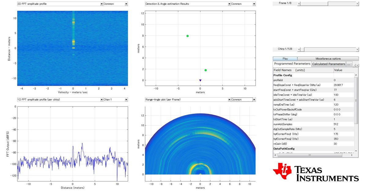
By referring to user guide and other threads, we are able to convert the raw data in correct format and get the same 1D FFT result as RadarStudio did (as shown below).

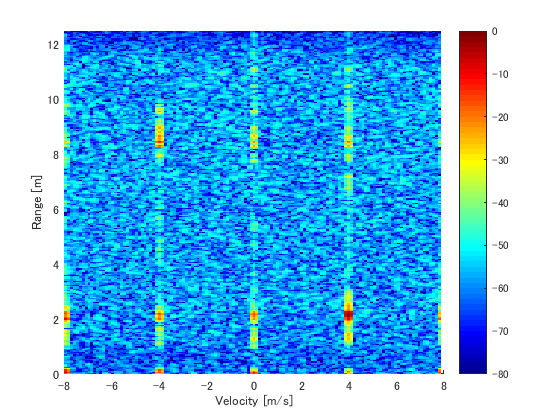
However, 2D FFT performed on the same raw data shows quite strange result. (There are only two static targets, however multiple targets with doppler velocities are obtained)

RadarStudio result:


Matlab 2D FFT result:

Could you please give some advice on this issue?

Thank you!

  • Hi,
    Could you provide more detail for this experiment?
    1. AWR1642 ES1/2.0?
    2. Have you used mmWave-Studio to configure the AWR1642 in development mode (SOP-2) or running mmw demo kind of application you have captured the data over LVDS using DCA1000?
    3. What is mmWave-Studio version?
    4. What is type of data input to this matlab processing script?

    Regards,
    Jitendra
  • Hi, Jitendra

    Thank you for your prompt response.

    As to your questions,

    1. AWR1642 ES1.0

    2. We used mmWave-Studio to configure the AWR1642 (SOP2 mode).

    3. The version of mmWave-Studio is 1.0.0.0

    4. We used a binary file named 'adc_data.bin' (obtained by DCA1000) as input to matlab.

    Below is the code we used to convert the raw data into correct format.

    clc
    close all
    clear variables
    %% global variables
    % change based on sensor config
    %----------------------------------------------------------------------
    numADCBits = 16; % number of ADC bits per sample
    numADCSamples = 512; % number of ADC samples per chirp
    numRx = 4; % number of receivers
    chirpSize = numADCSamples*numRx;
    numLanes = 2; % do not change. number of lanes is always 2
    isReal = 0; % set to 1 if real only data, 0 if complex data0
    %-----------------------------------------------------------------------
    %% read file
    % read .bin file
    fileName = 'adc_data.bin';
    fid = fopen(fileName,'r');
    adcData = fread(fid, 'int16');
    fclose(fid);
    fileSize = size(adcData, 1);
    % one chirp only
    %adcData = adcData(1:chirpSize,1);
    %% organize data by LVDS lane
    % for real data, each Rx in column
    if isReal
    LVDS = zeros(1, length(adcData(:,1)));
    LVDS = reshape(adcData(:,1), [], numRx);
    else
    % for complex data
    % LVDS row with half length
    LVDS = zeros(1, length(adcData(:,1))/2);
    % combine real and imaginary parts
    counter = 1;
    for i=1:4:fileSize-1
    LVDS(1,counter) = adcData(i) + sqrt(-1)*adcData(i+2);
    LVDS(1,counter+1)=adcData(i+1)+sqrt(-1)*adcData(i+3);
    counter = counter + 2;
    end
    % create column for each Rx channel
    if numRx > 2
    LVDS = reshape(LVDS(1,:), length(LVDS(1,:))/numRx, numRx);
    end
    end

  • I have solved the problem.
    There is something wrong with the matlab code for raw data conversion.