I have a question about the input circuit of FDC2112 for use in a differential type circuit like the one below (the datasheet talks about using a 18uH inductor, and 33pF):
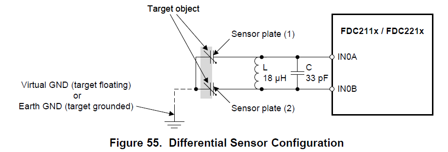
However, when looking at the layout, the 18uH inductor is quite big (physically) and my customer is struggling to fit it in their mechanics. They would like to use a physically smaller inductor. Can you explain how to choose or design the L-C tank circuit (18uH and 33pF)?
They are looking to sample at around 5MHz.