This thread has been locked.

If you have a related question, please click the "Ask a related question" button in the top right corner. The newly created question will be automatically linked to this question.

PGA460-Q1: PGA460-Q1 SPI communication issue

Part Number: PGA460-Q1
Other Parts Discussed in Thread: PGA460

Hello

I am trying to get a first communication with the PGA 460-Q1 via SPI interface at 1 MHz.

Test Pin tied to 0 -> 3.3 V logic IREG:  3.1V VPWR: 8.3V.

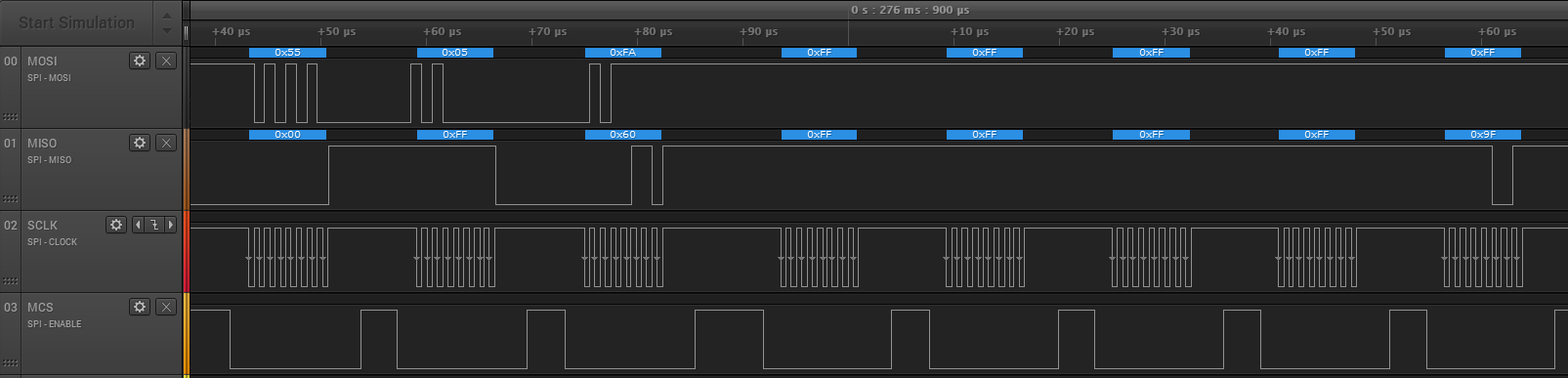
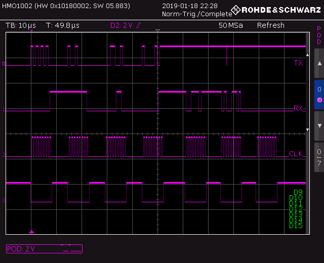
Clock is 0 and starts with rising edge. SPI is set to idle "Low" and sample on trailing edge.

Between every byte on SPI there is about 7 us gap on the transmission due to to the program flow.

When using the example for reading the reg INIT_GAIN from data sheet, transmitted data is as in data sheet, also the received data. 

So checksum calculation looks also to be correct.

When reading register  "DEV_STAT0" Register should read to 0x84.

Following data is transmitted (verified with oscilloscope) 0x9; 0x4C; 0xAA. Received is 0xFE; oxFF, 0xFF

I would have expected 0x00; 0x84; 0xChecksum, so this looks obviously wrong.

Any idea what to check or what could went wrong? Is the 7 us gap a problem?

Thanks


  • Olfu,

    We have received your question & will respond to you soon.
  • Olfu,

    The 7us gap between each byte should not be a problem. A note about the SPI from the datasheet: "In this mode the USART interface acts as a serial-shift register with data set on the rising edge of the clock and sampled on the falling edge of the clock."

    Your SPI Mode may need re-configuring. The PGA460 requires SPI in MODE 0: CPOL=0 CPHA=0

    You can refer to the PGA460 Energia Library and Code Example for an example on how SPI is implemented and used on the MSP430 MCU. Here is an example screen capture showing SPI in action during a Ultrasonic Measurement Result read command (command 5):

  • Hi Akeem
    I have setup the SPI so it matches the TX on your example screen, but RX answer is still 0x00, 0x00, Ox00.
    Is the sync byte 0x55 also necessary in the SPI mode ?

    The only condition where it looks the PGA 460 is responding when setting the Clock idle low and the sampling on rising edge. But hear the result does not mach with expected values of my example reading DEV_STAT0. Looks Like I need to experiment more with the settings of SPI.
    By the way I am working with a SiliconLabs ARM MCU so MSC430 Mode 0 might not match with my SPI setting.
    BR
    Oliver
  • Hi

    I digged deeper into the SPI modes and get a little bit infused based what I find in your statement and in the programming example.

    So you recommend SPI_Mode 0 like in the examples, however when I look at the data sheet page 41 where it is stated

    "... data set on the rising edge of the clock and sampled on the falling edge of the clock. ..." this correspondents to a SPI mode 1 . Also here the clock is idle Low, where your example clock is idle high which would correspond to SPI mode 2.

    Testing my application only in SPI-mode 0 I see a receive signal different from 0x00, 0x00, 0x00.

    However the data I get is somewhat confusing. TX is based on rising edge as SPI 0 indicates, RX is unclear on rising edges but 0xDC on falling edges.

    Last received byte is 0x00 with is not the checksum of the received data.

    Is 0x55 in sync mode realy required?

    Any explanations ?

    BR

    Oliver

    TX 0x55 on rising edge

    RX 0xDC on falling edge, unclear on rising edge 

    full sequence TX 0x55,0x9,0x4x,0xA1   RX 0xDC on falling edge

  • Hello Bharat Aravamud

    I have solved the issue, your answer was a a bit confusing as mentioned above.
    I had an additional bug in the data that was passed to checksum function. After correcting this, SPI mode 0 still did not work.
    At e2e.ti.com/.../731991 I found a detailed setup of SPI, and it says SPI mode 2 not 0 as you stated. After implementing SPI Mode 2 it worked well.
    BR
    Oliver