


Other Parts Discussed in Thread: AWR1642, DCA1000EVM
Tool/software: TI-RTOS
Before I solder on a 0 ohm resistor to enable the HW trigger on my AWR1642 ES1.0 device, I want to verify that this is the appropriate location for such a jumper. According to the schematic, R165 is here highlighted in blue:

On the device, that would correspond to this location (small green circle). From observation, it does not seem that there is a resistor present, so this would make sense.
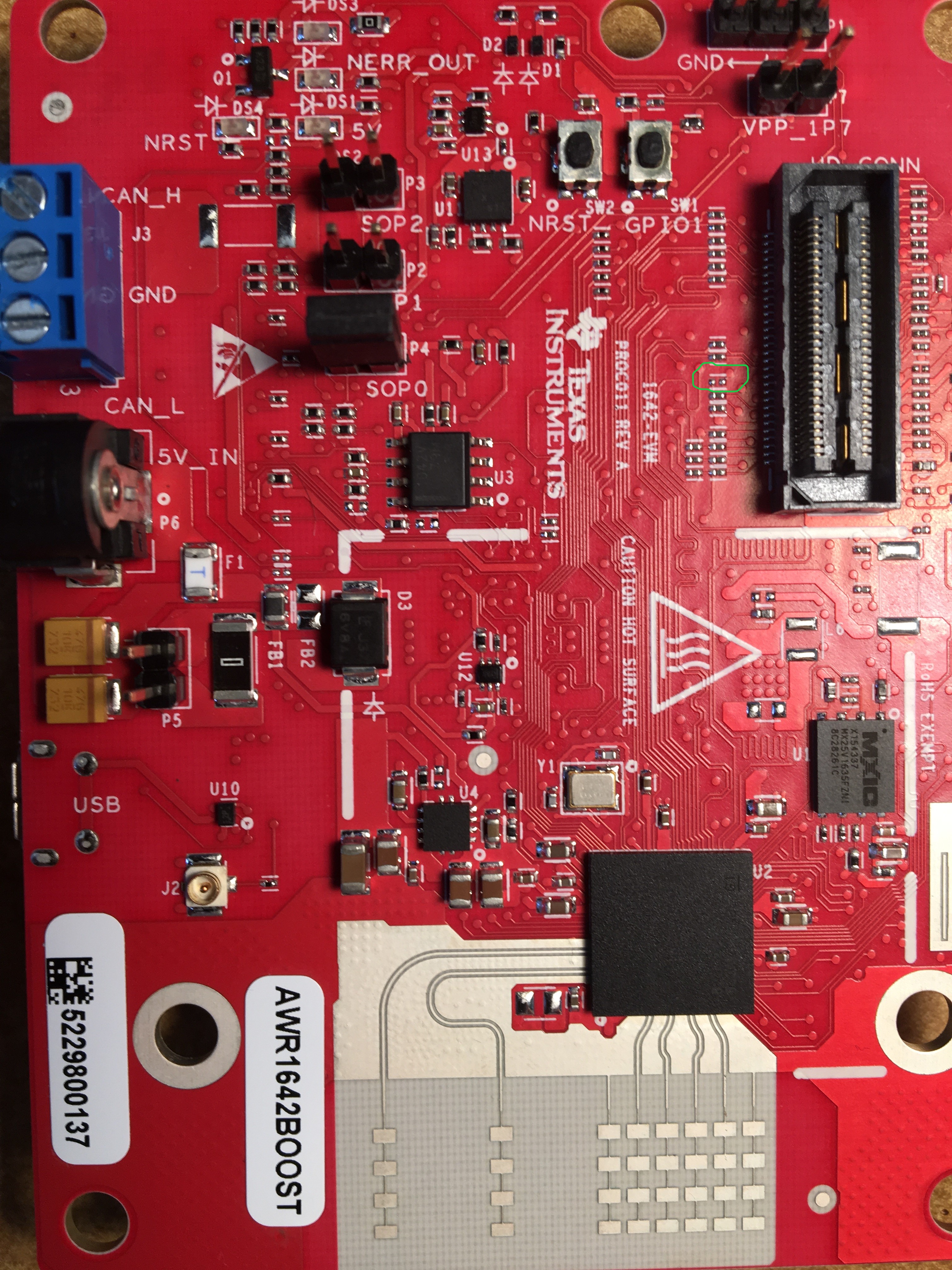
Could you please confirm this will work? Furthermore, will there be any issues capturing LVDS data from a connected DCA1000EVM if I solder a resistor in this place?
