This thread has been locked.

If you have a related question, please click the "Ask a related question" button in the top right corner. The newly created question will be automatically linked to this question.

AWR1843 Chirp Parameters Assistance

Other Parts Discussed in Thread: AWR1843

We recently ran into an issue with our AWR1843 hardware version that uses the TI ODS antenna pattern, see below. We’re running a modified version of the MRR demo that TI provided. We had to modify the angle estimation to work with the ODS antenna and we’re now trying to change the chirp profile to determine the effects in distinct scenarios.


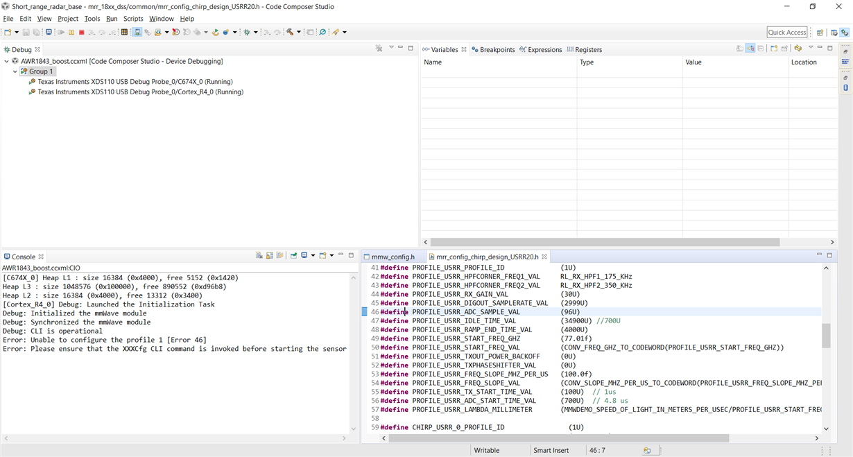
Starting with the USRR parameters for our base, we tried to modify the sampling rate (and the ramp end time to compensate), but we keep running into a RL_RET_CODE_PF_FREQ_SLOPE_1NVAL_IN error (cli error 46). We ensured that the numbers work to the best of our ability, but there aren’t any more details about this error other than the frequency slope being invalid. Given that the actual slope is unchanged, we are wondering if TI has any more details or ways to debug this issue.


For reference, we took the USRR20.h configuration, and changed the PROFILE_USRR_DIGOUT_SAMPLERATE_VAL to 5376U and the PROFILE_USRR_RAMP_END_TIME_VAL to 13300U. This is the error that we got from the debugger. We interpreted the error as the RL_RET_CODE_PF_FREQ_SLOPE_1NVAL_IN by referencing the AW1xx_Radar_Interface_Control Document: https://e2e.ti.com/cfs-file/__key/communityserver-discussions-components-files/1023/AWR1xx_5F00_Radar_5F00_Interface_5F00_Control.pdf. This error is thrown by rlSetProfileConfig API function, which returns a value of type rlReturnVal_t, described in section 10.6.7 of this document.


  • Just a note, I've described the configuration that caused the original error above: PROFILE_USRR_DIGOUT_SAMPLERATE_VAL to 5376U and the PROFILE_USRR_RAMP_END_TIME_VAL to 13300U, but the above screenshot shows another configuration that causes the same error.
  • Hi Manny,

    Yes, it is difficult to modify a chirp configuration by hand unless you are an expert. What are you trying to achieve with the changes above?

    It is likely that the changes resulted in more than one conflict, and the conflict that got reported was not the most intuitive of the problems. By increasing the ramp time by so much and not lowering the slope, my guess is that you exceeded the 4GHz bandwidth. But by increasing the sampling rate, you don't need as long of a ramp, so I'm not sure of the utility of increasing the ramp time. The difficulty is the interplay of all of the parameters, of course.

    -dave
  • Hello Manny,

    As indicated by Dave , your current configuration of changing the RAMP_END time value and the SAMPLE_RATE goes beyond the available bandwidth. 

    Bandwidth based on your configuration  = Ramp_END_TIME * Slope = 133us * 42e12 = ~5.5GHz

    We typically keep the ADC sample value multiple of 2 as it is easy for algorithm computation. That is the reason we have a "PROFILE_USRR_ADC_SAMPLE_VAL = 512" . If you change this value then you will need changes in  the processing chain as well to perform the computation right with available sample value.

    You can change your configuration as below :

    PROFILE_USRR_DIGOUT_SAMPLERATE_VAL    (5800U)

    PROFILE_USRR_RAMP_END_TIME_VAL              (9500U)

    Few caveats to keep in mind:

    PROFILE_USRR_RAMP_END_TIME_VAL   > ((PROFILE_USRR_ADC_SAMPLE_VAL/(PROFILE_USRR_DIGOUT_SAMPLERATE_VAL *1000)) + PROFILE_USRR_ADC_START_TIME_VAL)

    I would recommend you to get use the "mmWave Sensing Estimator" to arrive at the parameters for your configuration. The estimator will provide you with feedback on any errors in the paramters. 

    Let me know if you would need any further information.

    Thanks,

    Raghu

  • Manny, any updates? If not let's close the thread.