This thread has been locked.

If you have a related question, please click the "Ask a related question" button in the top right corner. The newly created question will be automatically linked to this question.

TDC7201: Higher raw sample rate in multi cycle average mode

Part Number: TDC7201

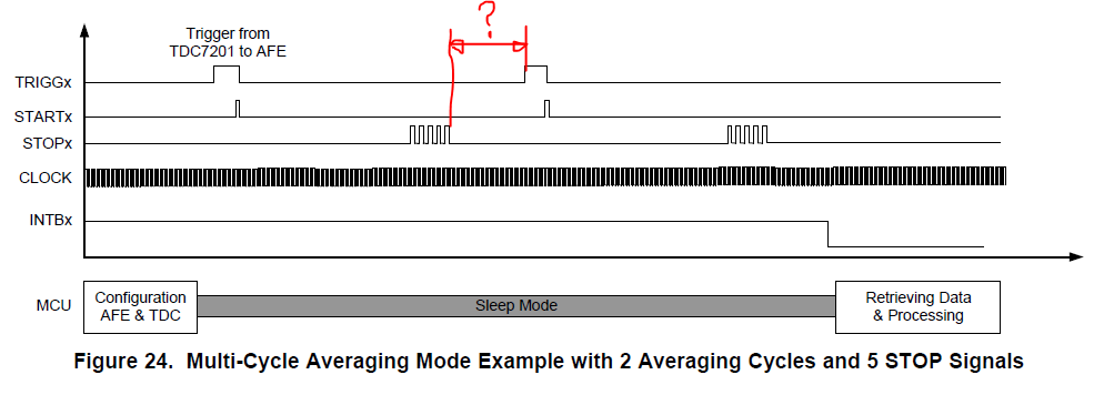
I understand that multi cycle average is for saving processing power and thus potentially saving energy when putting the MCU into sleep mode longer. But can the multi cycle average mode also be used to get a higher pulse repetition rate by saving SPI transfer time between individual measurements? Even though I will not get the raw measurements, this could still improve final accuracy because as we know the key to accurate LIDAR measurement is to average as much as possible.

This is the theory, but is this really faster by means of raw measurements per second? In the datasheet ther is no no definition of processing time in multi cycle average mode:

Thanks

Urs

  • Urs,

    I will respond to your question soon.
  • Urs,

    Note that there is a min time between a START & STOP signal as well as between 2 STOP signals. The SPI transfers the data post a multicycling averaging cycles and then transfers the data to the MCU.
  • Hi Bharat,

    thanks, I'am Aware of this, but this does not answer the question.

    I only use 1 STOP Signal and min time between START & STOP being 12ns. But far more time is used by processing time (~12us?) ans SPI Transmission time to MCU(~5.5us).

    So can I have a higher sample rate with multicycle average mode because of SPI Transmission is only every 128th measurement?

    How about processing time in multicycle average mode, is this also after every measuerement or only at end of multicycle?

    Urs

  • Hi Urs,

    Yes, an advantage of the multi-averaging mode would be that you don't have to have a SPI transfer for every measurement. As you already noted that you are aware of the timing restrictions. As long that that satisfies your measurement you should get higher throughput.

    From a device processing time perspective, it remains the same since the timing requirements need to be followed from table 6.3. The SPI transfer time is saved. There is some time between the last measurement and when the INTB pulse goes low. That time is not documented you will need to measure it in your setup.

    From the spec section 7.4.4 :
    TOFn = normLSB [TDCx_TIME1 - TDCx_TIME(n+1)] + [TDCx_CLOCK_COUNTn >> log 2 (AVG_CYCLES)] x [CLOCKperiod]

    the MCU has to calculate ToF by averaging (or right shifting) TDCx_CLOCK_COUNTn register reading by log2(Avg cycles). Basically the device just adds the the Clock Count for every cycle and MCU just averages it by right shifting.

    Regards,

    Vaibhav
  • Thanks a lot Vaibhav!

    One question remains. In the datasheet, Figure 24 Shows a delay between STOP Signal and Start of new measurement. Where does this delay come from and how long is it?

    Regards,

    Urs

  • Urs,

    There is few cycle time between the last expected STOP & TRIGG, at this time we do not have the exact time for this delay.