Other Parts Discussed in Thread: MMWAVE-STUDIO, AWR1243
Hi,
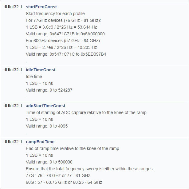
I try to find out the limit of the IWR6843 Chip but I can't find a documentation that gives me the limit for the chirp parameter e.g. slope. In the following document I found some hints

but I can only make suggestions of the limits.
In this document
they mentioned a chirp timing parameter configuration calculator utility in Radar Studio application available as part of the DFP Packages but I can't find this tool in the Package.
The Doxygen documentation seems also not very helpful. Is there a documentation of the RF-parameters with their limits?
Also for my application I like to know/control the time when a chirp (or a sequence of chirps) starts in my application as good as possible. Is there a way to control the start of the chirp from the application exactly?
Regards,
Martin