Other Parts Discussed in Thread: TIDA-01570,
Tool/software: Code Composer Studio
Hi,
When we do the range detection by the mmWave studio, the scenario is as follows,
1. the max. range detection is set at 50m
2. Place one corner reflector in front of RADAR sensor, the distance is 5m and 10m
the result is :
For TI EVM:
5m corner reflector:
1D FFT plot appears one peak at 5m
10m corner reflector:
1D FFT plot appears one peak at 10m
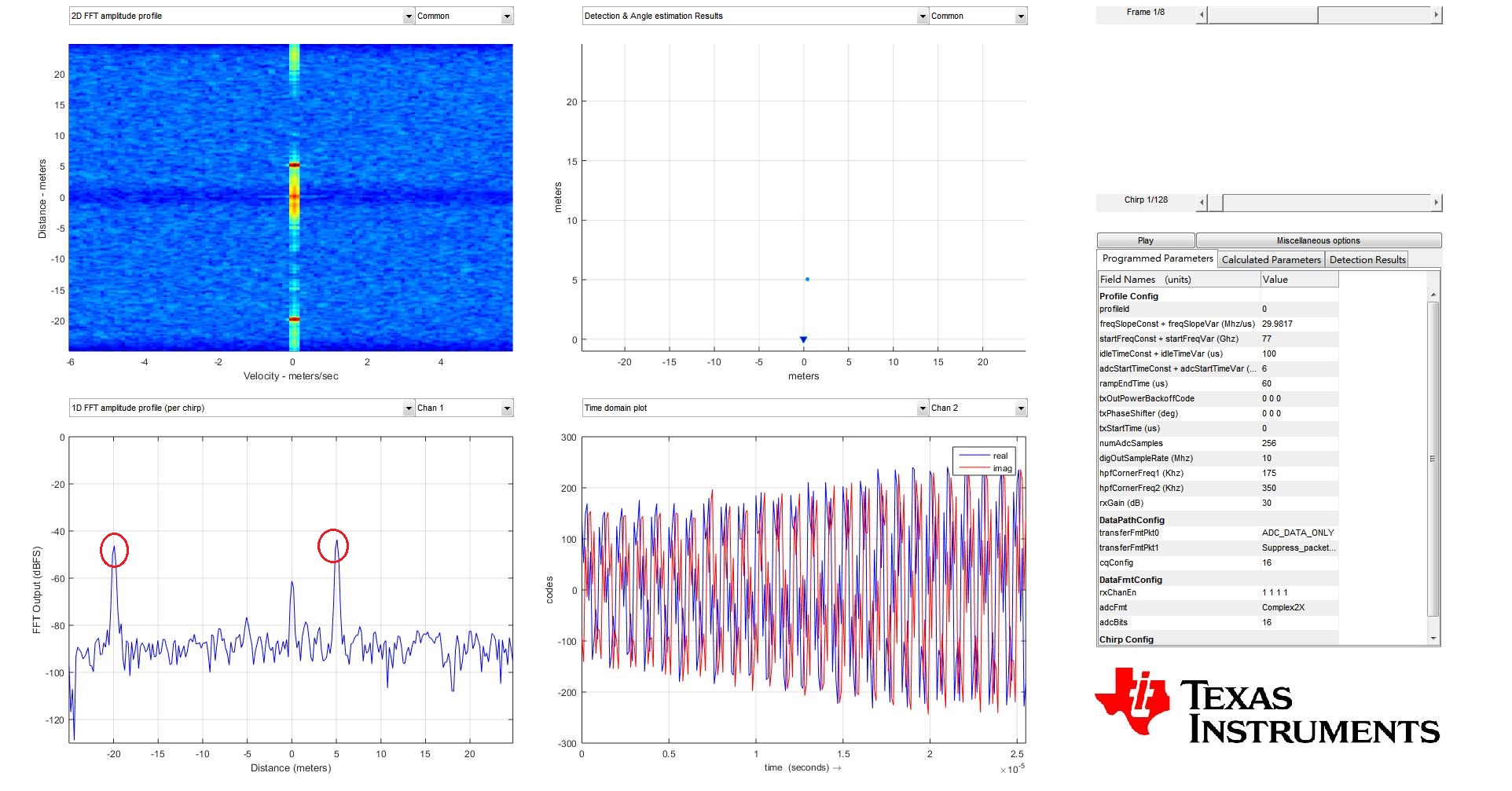
Our RADAR board:
5m corner reflector:
1D FFT plot appears two peaks at 5m and -20m (see the attached file, corner5m)
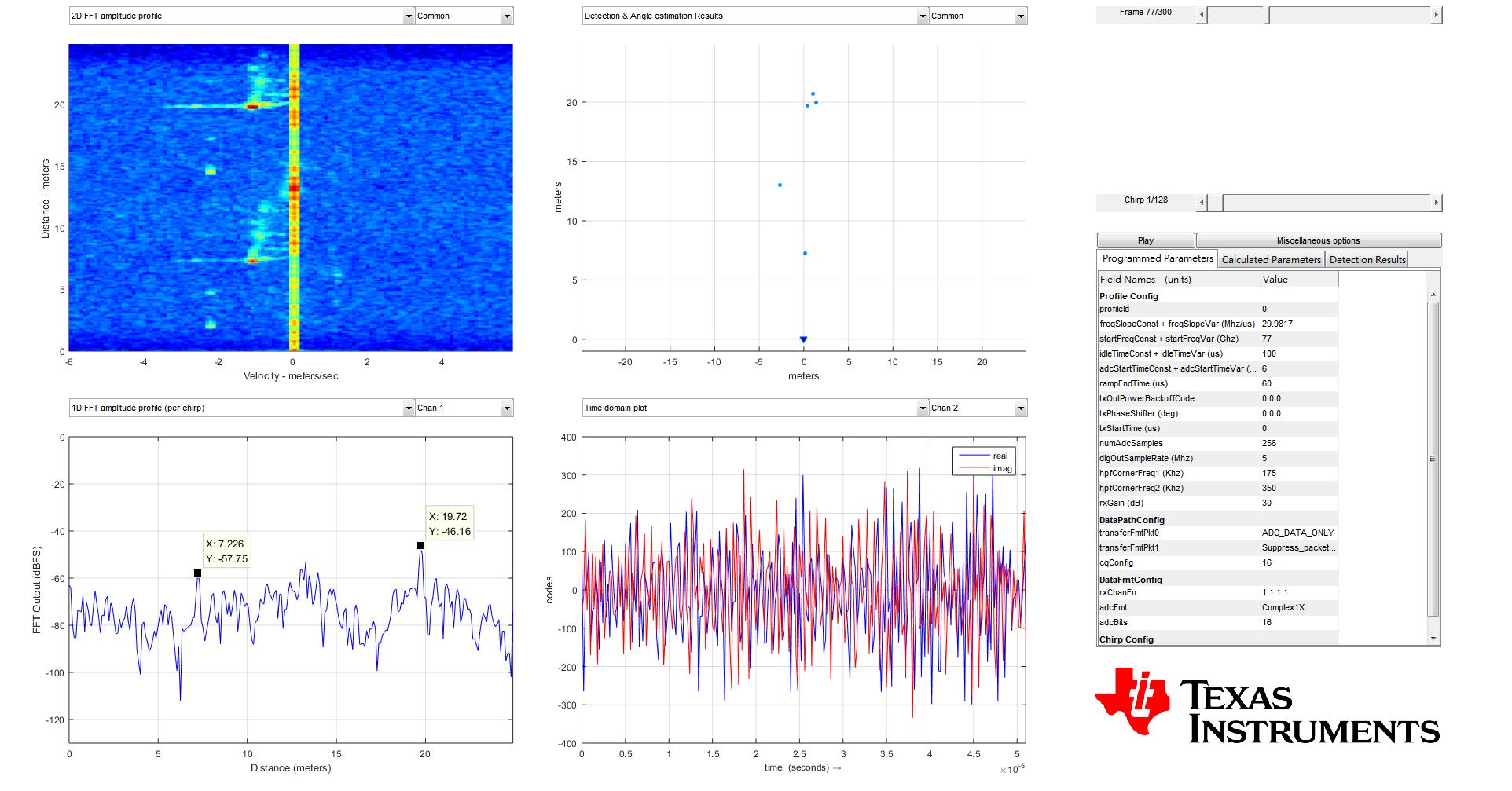
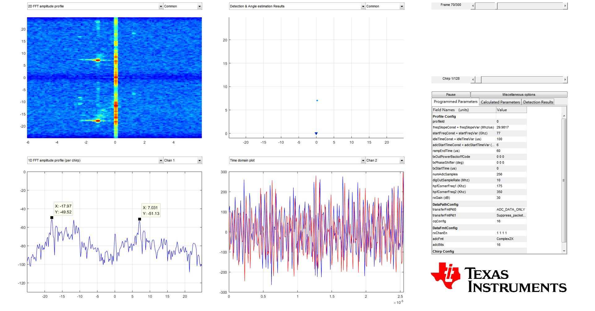
10m corner reflector:
1D FFT plot appears two peaks at 10m and -15m (see the attached file, corner10m)
Why does the minus range appear ? Could you provide the cause that results this phenomenon for us ?
Thanks
Michael Su