This thread has been locked.

If you have a related question, please click the "Ask a related question" button in the top right corner. The newly created question will be automatically linked to this question.

IWR1642: mmWave Sensing Estimator does not accept TI published chirps

Part Number: IWR1642
Other Parts Discussed in Thread: MMWAVE-STUDIO, IWR6843ISK

Hello,

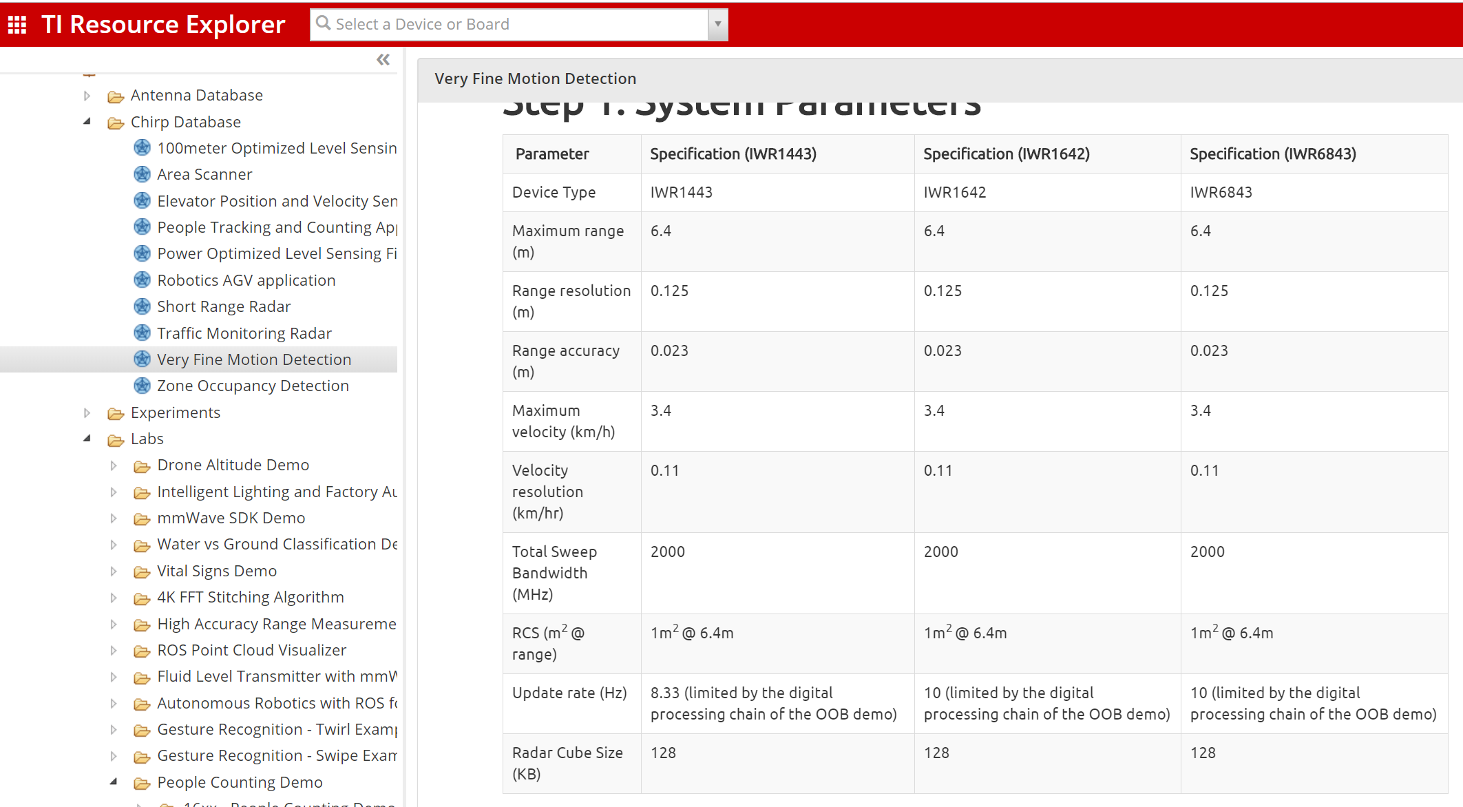
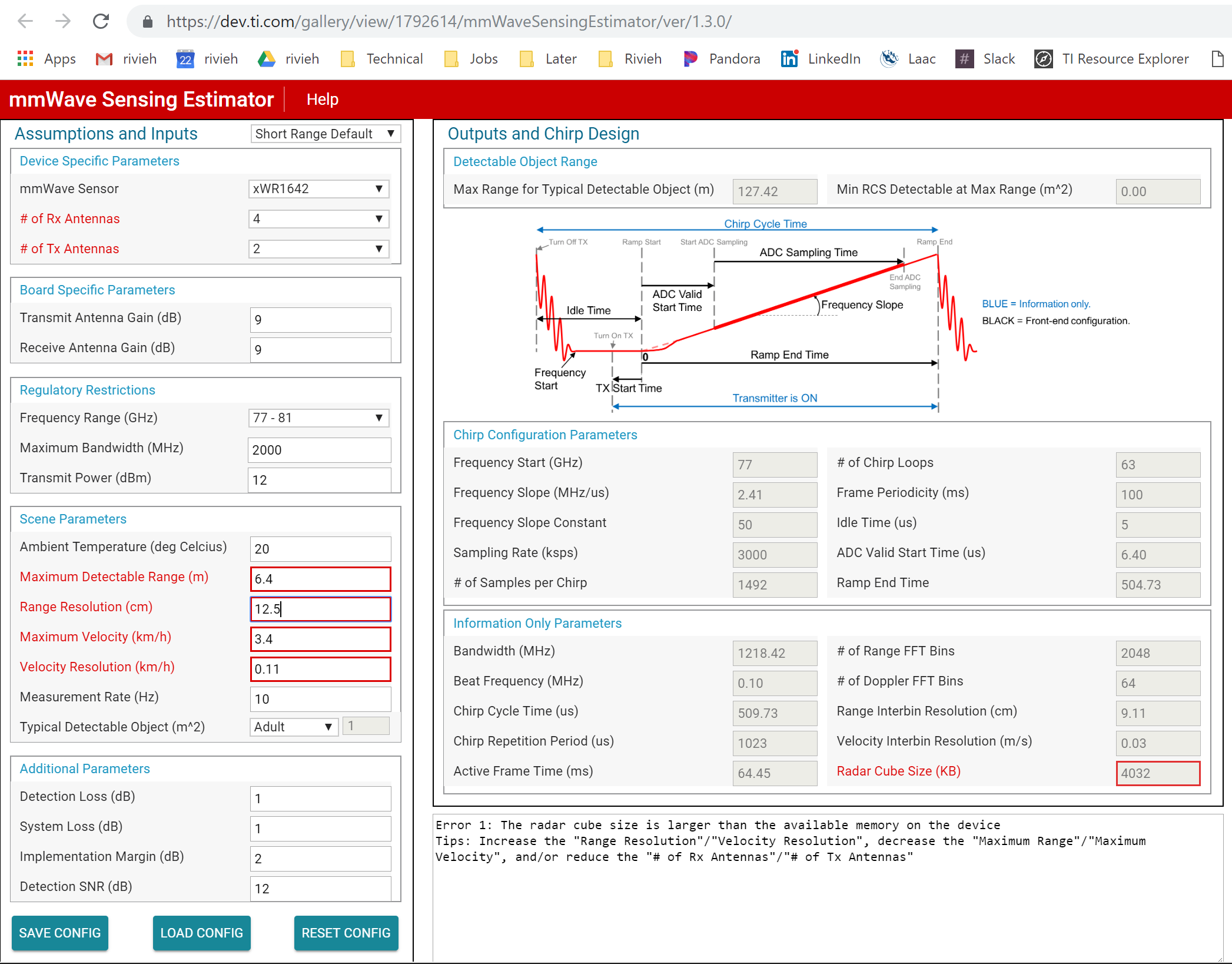
I am having trouble with mmWave sensing estimator generating chip settings using input parameters that I believe to be acceptable. So to debug the issue, I plugged in input parameters from one of the chips listed under the industrial toolbox chip database (fine motion) and I am still getting an error. I am assuming the chip published in the industrial toolbox are valid chip so I am not sure if I am doing something wrong. Attached are the screenshots of the chip I am trying to configure (fine motion for IWR1642) and the sensing estimator inputs/output.

Thanks! Mustafa

  • Hi Mustafa,

    This particular fine motion detection chirp was not generated with mmWaveSensingEstimator which is the reason we have provided the chirp configuration file directly on the chirp web page instead of linking with the Sensing estimator.

    It has to do with how we achieve the high velocity resolution needed for this application. The fine motion detection chirp provides a very high (i.e. lower actual value) velocity resolution and Vres is defined as:

    Vres = Lambda / 2 x Active_frame_time

    Where Active_frame_time = Number of chirps x Chirp time (i.e. Tc). So Velocity resolution depends upon Chirp time and the number of chirps. There are a few ways to achieve the required chirp time.

    Approach 1: Sensing estimator generates a chirp with the Minimum idle time (5us in this case) so the rest of the ramp time (about 500us) consists of active sampling time resulting in a very high number of samples i.e. 1492 samples. This results in the huge memory requirement you see with the Sensing Estimator.

    The other way to achieve the same Vres is by increasing the idle time and keeping a very low active sampling time. This is the approach followed in the actual chirp config file where we have 500us of Idle time and only about 16us of active sampling time (since the range requirement is very low, only 6.4m) requiring a low number of ADC samples in the profileCfg command (64 samples). This way we achieve the large Chirp cycle time while still keeping a low memory requirement.

    Please mark the thread resolved if this answers your question otherwise get back if you have more questions.

    Thanks

    -Nitin

  • Thanks Nitin for the detailed explanation. I understand why I couldn't just plug-in the fine motion chirp parameters to the sensing estimator. It looks like this tool doesn't allow me to change the idle time and many other configuration parameters.

    At the bottom line, I am looking for a tool that can verify my custom chirp settings (make sure L3 memory is not too big, bandwidth is within 4GHz, ADC sampling is not too high, etc.) and preferably auto generate SDK configuration commands based on those settings. I thought the mmWave sensing estimator will do just that but it looks like this tool is limited and doesn't allow me to change all the parameters I can change in the code (ex: idle time, chirp time, sampling rate, etc). Are there any other tools or a spreadsheet that TI offer which could help?

    Thanks!
    Mustafa
  • Hi Mustafa,

    You can do so using MMWAVE-STUDIO which is the tool for Raw ADC data capture and post processing. You will need the DCA1000 data capture card to work with MMWAVE-STUDIO (in addition to the MMWAVE-ICBOOST and IWR6843ISK).

    Please look at the following training video for an overview of the process:

    TI training: Raw ADC Data capture using DCA1000 Board and mmWave Studio

    Thanks

    -Nitin