This thread has been locked.

If you have a related question, please click the "Ask a related question" button in the top right corner. The newly created question will be automatically linked to this question.

FDC1004EVM: Liquid level sensing using the GUI for the fdc1004evm

Part Number: FDC1004EVM
Other Parts Discussed in Thread: FDC1004

Hello,

I have tried to use the fdc1004 board to measure the level of liquid inside a bottle. There are several application notes that states how to do so and I am almost sure I have done it correctly. 
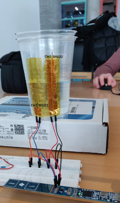
The way I did it was to make 2 electrodes for a level sensor and 2 electrodes for a REF sensor. I made these from copper foil tape. the level sensor is approximately 8 cm and the REF is about 1.5 cm.
I have connected one of the levelsensing electrodes to cin1 and the other to shield2 and for the REF, I have connected one to Cin2 and the other to shield1. 
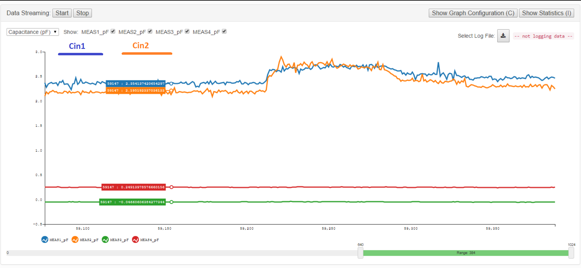
But for some reason, I cant seem to get a difference in the GUI's capacitive measurement. I can get an instant respons but as soon as I stop puring water, it kind of resets and go back to the capacitive output it was at at the beginning. 
Am I doing something wrong or is there a reset function that I cant find in the GUI?

Thanks in advance! 

  • This device does not have a reset function, it will tell you the absolute capacitance. Can you take a picture of your set-up?
  • Thank you,

    My test looks like this and I have attached the results from the GUI when puring water into the glass.

    As you can see, it doesn't act like it should or at least doesn't get a steady capacitance change.

  • Are you trying to do the out of phase technique shown in this app note?

    www.ti.com/.../snoa925.pdf

    Is this configured as a differential measurement?

    CIN1 (SHLD 1) - CIN4 (SHLD 2)
    CIN2 (SHLD 2) - CIN4 (SHLD1)

    If you are doing this with a single-ended measurement, then it makes sense that you would not see much of a response. In a single-ended measurement, the SHLDx signals are tied together and they are forced to the same potential as the CINx driving circuit. For a single-ended measurement, the SHLDx electrodes should be connected to ground to form something similar to Figure 1 in the linked app note (but without the shield layer).
  • Hello Clancy,

    Thank you very much for your answer.
    Im sorry, I didn't respond right away, but I needed to test once again to make sure I did it like, u just told me in the previous respond.

    I have now tried the conventional approach and it worked. 
    Here I connected:
    REF1 - Cin4,
    REF2 - GND,
    LEVEL1 - Cin1,
    LEVEL2 - GND

    And I got a response when i Pured liquid in the cup.

    The actual approach, which Im trying to do is the out of phase technique.
    Im not sure I understand how each electrode should be connecte, because as I understand it, this is the electrodes I need to have in order to shield it.

    REF1
    REF2
    LEVEL1
    LEVEL2
    ShieldREF1
    ShieldREF2
    ShieldLEVEL1
    ShieldLEVEL2

    Is this correctly understood or do I need to do it differently?

    Thank you :)