Other Parts Discussed in Thread: DRV421
Dear TI engineer,
I designed a current sensor based on DRV411 which has the same diagram to the datasheet. When I measuring the gain vs. frequency, I found that the gain drops down between 300Hz to 2kHz. I measured the inductance of coil from 100Hz to 100kHz, the value is all about 25mH, and the resistance of coil and shunt is 22.5 ohm overall.
The IP parameter is:
IP DC=1A, IP AC (P-P)=1A
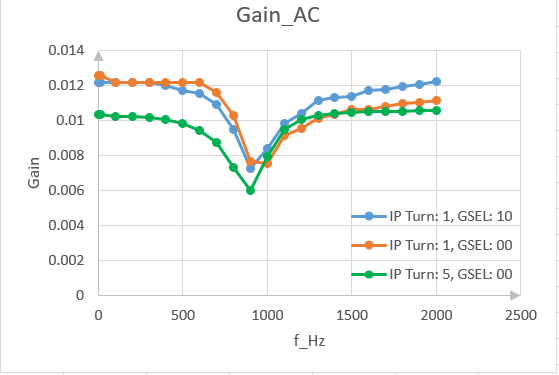
I record the test data and draw the curve in three configurations like below.
1. IP Turn: 1, GSEL: 10
2. IP Turn: 1, GSEL: 00
3, IP Turn: 5, GSEL: 00
The detailed curve like below. The gain in DC and high frequency is different between configurations are due to the IP is very small which can lead to reading errors.
You can see that the corner frequency of current transformer is about 900Hz. But according to the theory, the corner frequency equal to f=R/(2pi*L)=22.5/(6.28*0.025)=143Hz. It is much different from the actual test value.
Could you to give me some ideas to help me to understand this?