Other Parts Discussed in Thread: BOOSTXL-PGA460, PGA460
Hi, we are developing a proximity warning system with PGA460-Q1 devices.
The design is closely based on the BOOSTXL-PGA460 design. The transducer (40Khz) and Transformer(TDK-EPCOS - B78416A2232A003) are on a separate board, just like the BOOSTXL board.
Our design has 4 PGA460 devices with each having its own dedicated UART. Hence we don’t use the addressing scheme. The PGAs are powered by a 9V 1Amp on board power supply (switch mode).
We have verified that each PGA receives the same settings during initialisation (by using the Bulk EEPROM read command).
The EEPROM settings are as follows:
;GRID_USER_MEMSPACE
00 (USER_DATA1),00
01 (USER_DATA2),00
02 (USER_DATA3),00
03 (USER_DATA4),00
04 (USER_DATA5),00
05 (USER_DATA6),00
06 (USER_DATA7),00
07 (USER_DATA8),00
08 (USER_DATA9),00
09 (USER_DATA10),00
0A (USER_DATA11),00
0B (USER_DATA12),00
0C (USER_DATA13),00
0D (USER_DATA14),00
0E (USER_DATA15),00
0F (USER_DATA16),00
10 (USER_DATA17),00
11 (USER_DATA18),00
12 (USER_DATA19),00
13 (USER_DATA20),00
14 (TVGAIN0),8D
15 (TVGAIN1),EE
16 (TVGAIN2),EF
17 (TVGAIN3),10
18 (TVGAIN4),A5
19 (TVGAIN5),20
1A (TVGAIN6),C0
1B (INIT_GAIN),C0
1C (FREQUENCY),32
1D (DEADTIME),00
1E (PULSE_P1),08
1F (PULSE_P2),16
20 (CURR_LIM_P1),47
21 (CURR_LIM_P2),7F
22 (REC_LENGTH),1B
23 (FREQ_DIAG),00
24 (SAT_FDIAG_TH),EE
25 (FVOLT_DEC),7C
26 (DECPL_TEMP),0B
27 (DSP_SCALE),00
28 (TEMP_TRIM),00
29 (P1_GAIN_CTRL),00
2A (P2_GAIN_CTRL),C1
2B (EE_CRC),39
40 (EE_CNTRL),00
41 (BPF_A2_MSB),87
42 (BPF_A2_LSB),07
43 (BPF_A3_MSB),F3
44 (BPF_A3_LSB),72
45 (BPF_B1_MSB),06
46 (BPF_B1_LSB),47
47 (LPF_A2_MSB),7E
48 (LPF_A2_LSB),67
49 (LPF_B1_MSB),00
4A (LPF_B1_LSB),CD
4B (TEST_MUX),00
4C (DEV_STAT0),80
4D (DEV_STAT1),00
5F (P1_THR_0),44
60 (P1_THR_1),44
61 (P1_THR_2),44
62 (P1_THR_3),44
63 (P1_THR_4),55
64 (P1_THR_5),55
65 (P1_THR_6),9C
66 (P1_THR_7),D4
67 (P1_THR_8),72
68 (P1_THR_9),10
69 (P1_THR_10),63
6A (P1_THR_11),28
6B (P1_THR_12),30
6C (P1_THR_13),34
6D (P1_THR_14),3C
6E (P1_THR_15),00
6F (P2_THR_0),BC
70 (P2_THR_1),BC
71 (P2_THR_2),CC
72 (P2_THR_3),EC
73 (P2_THR_4),CC
74 (P2_THR_5),CC
75 (P2_THR_6),FC
76 (P2_THR_7),D4
77 (P2_THR_8),A5
78 (P2_THR_9),29
79 (P2_THR_10),4D
7A (P2_THR_11),73
7B (P2_THR_12),73
7C (P2_THR_13),73
7D (P2_THR_14),73
7E (P2_THR_15),07
7F (THR_CRC),15
EOF
We see a large variation on the echo data dump for the different PGA devices in spite of them being mounted on the same board, powered by the same power supply.
Our question being, is it normal to see a large variation on signal between two PGA devices sharing the same settings and Power Supply.
Kindly note that while running the Data dump, each PGA was run alone. Meaning, no two PGAs were sampling data at the same time.
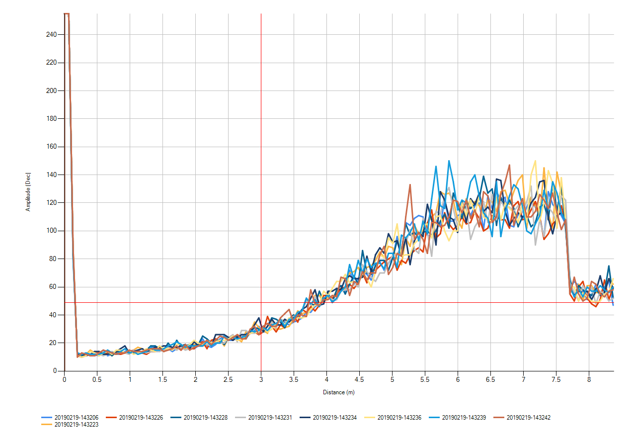
The above EDD is for what I will call PGA1, using Sensor Board 1
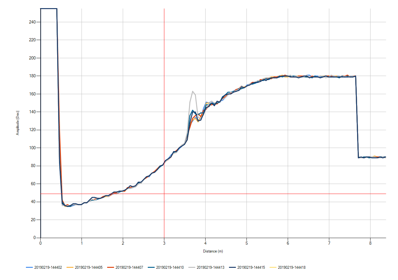
The above EDD is for what I will call PGA3, using Sensor Board 1. Kindly note that both echo data dumps were taken on an empty field of view.
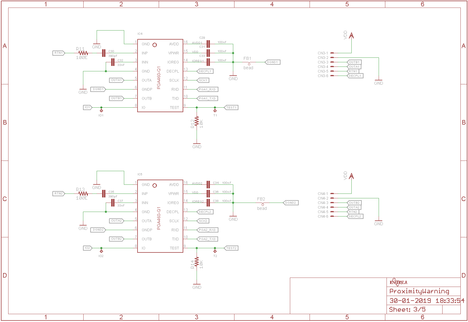
The schematic for the PGA section is attached below