This thread has been locked.

If you have a related question, please click the "Ask a related question" button in the top right corner. The newly created question will be automatically linked to this question.

DRV5032: Web-Tool output values Vs. Observed - what assumptions / values is the tool using

Part Number: DRV5032


Hello Hall sensor gurus!

I have this question (and observations) from my customer:

Using DVR5032FB

Using NdFeB Grade 42 Cylinder  6.35mm x 6.35mm (0.25” x 0.25”)

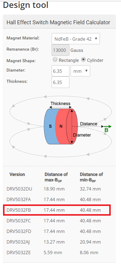
Here is what the design tool says I will get in performance.

Converting this to inches, that’s 0.72” for Bop and 1.59” for Brp

OK, I have a prototype working, and here is what I am getting empirically:

Bop = 0.85”

Brp = 1.05”

Question: The tool tells me I will have hysteresis in the range of 1.22” but I am only seeing hysteresis of 0.2”

That is a huge difference. Can you explain to me why I need to make sure Brp is so far away?

In my design, if I have to go 1.22” away from trigger point to make sure the IC shuts off, it doesn’t work for me.

I need help with this. Please advise.

-------------------------------------------

I did a quick calculation using equation 2, page 16 from the datasheet, and it looks like the customer values line up very nicely with the Typical BOP and BRP values. So, it looks like the measurement was done properly... 

Please comment on the Web tool values more and address the customer concerns about the maximum hysteresis value they can expect.

Thanks!

  • Hello Mark,

    Thank you for reaching out to us! I think you may have had a typo with some of your numbers. For max Bop I get 0.69", and I still also get 1.59" for min Brp. That puts the distance between these two at 0.9", which is still quite a bit larger than the 0.2" that you measured.  The reason for this big difference is because the calculator tool uses the MAX Bop and the MIN Brp, not the typical values:

    As you observed, you will typically have a smaller hysteresis travel distance as the sensors will often reflect the typical values.  The reason the calculator uses the extremes to to make sure that your system always works no matter what the variation of your individual part is.  

    If the 0.9" is still too much travel distance for you then you have a couple options.

    1) If you can't change anything in your design (or don't want to), then you could test individual sensors and filter out the ones that won't work for you.

    2) If you can still make design changes, and if you need a smaller travel distance for the hysteresis curve, then you can change the magnet orientation to move sideways over the sensor as in this photo:

    This can give you a fair amount of control over the hysteresis travel distance because the magnetic field is 0mT when the magnet is directly over the sensor and gets stronger as the end of the magnet gets over the sensor.  You can adjust the travel distance by adjusting the distance from the magnet and the length of the magnet.  The magnets strength will also come into play of course.  One thing to note is that the center band near 0mT where the sensor is guaranteed to be off is usually fairly narrow.  One way around this is to use a unipolar version of the DRV5032 (DU or FD).  This way  if you pass the 0 point then the sensor will still be off.  

    The calculator tool on our web page will not help you design  for this angle, but you can use another calculator such as the one found here: https://www.kjmagnetics.com/fieldcalculator.asp 

    With this calculator you can put the "sensor" at any position relative to the magnet and look at the specific field (Bx or By) through the sensor.