This thread has been locked.

If you have a related question, please click the "Ask a related question" button in the top right corner. The newly created question will be automatically linked to this question.

LDC1614EVM: GUI

Part Number: LDC1614EVM

Dear Clancy and Bala

Here are my questions for LDC1614EVM.

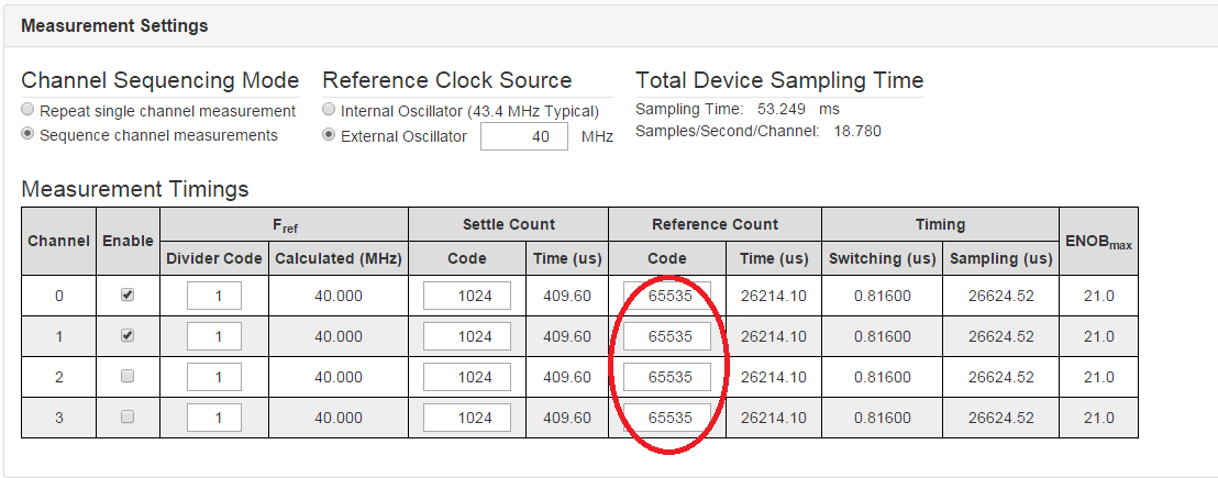
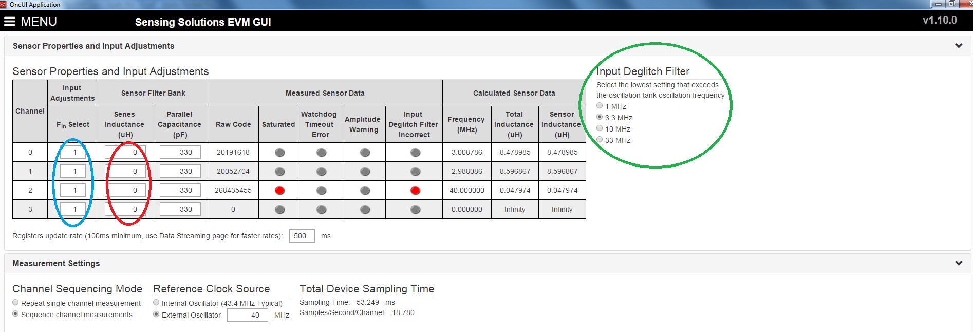
1. In GUI, there is Channel Sequencing Mode. Does choosing the "Repeat single channel measurement"  measure 1 channel only and choosing "Sequence channel measurement" measures multiple channel?

2. What is the maximum Reference Count? Is 65535 a default value?

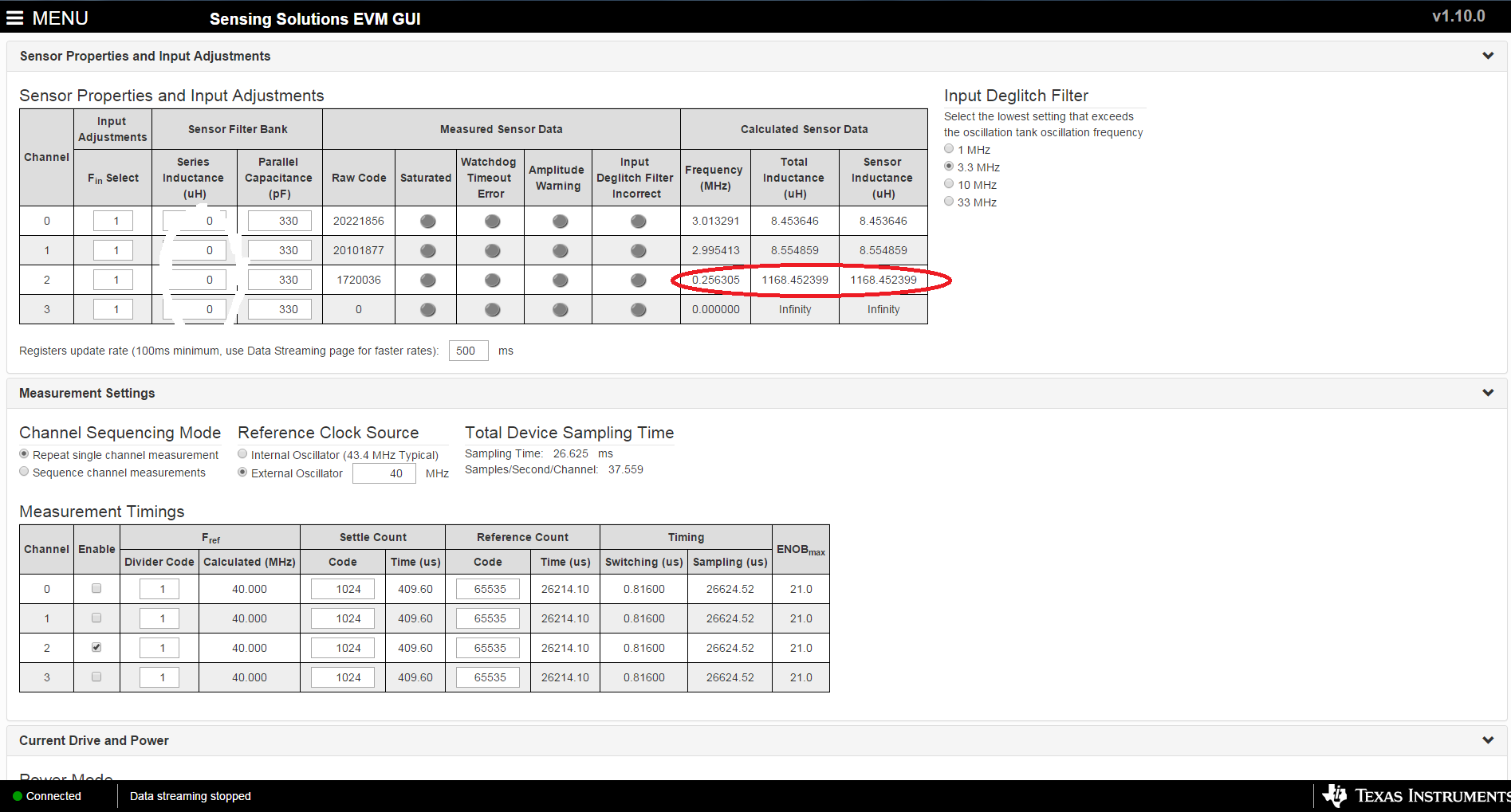
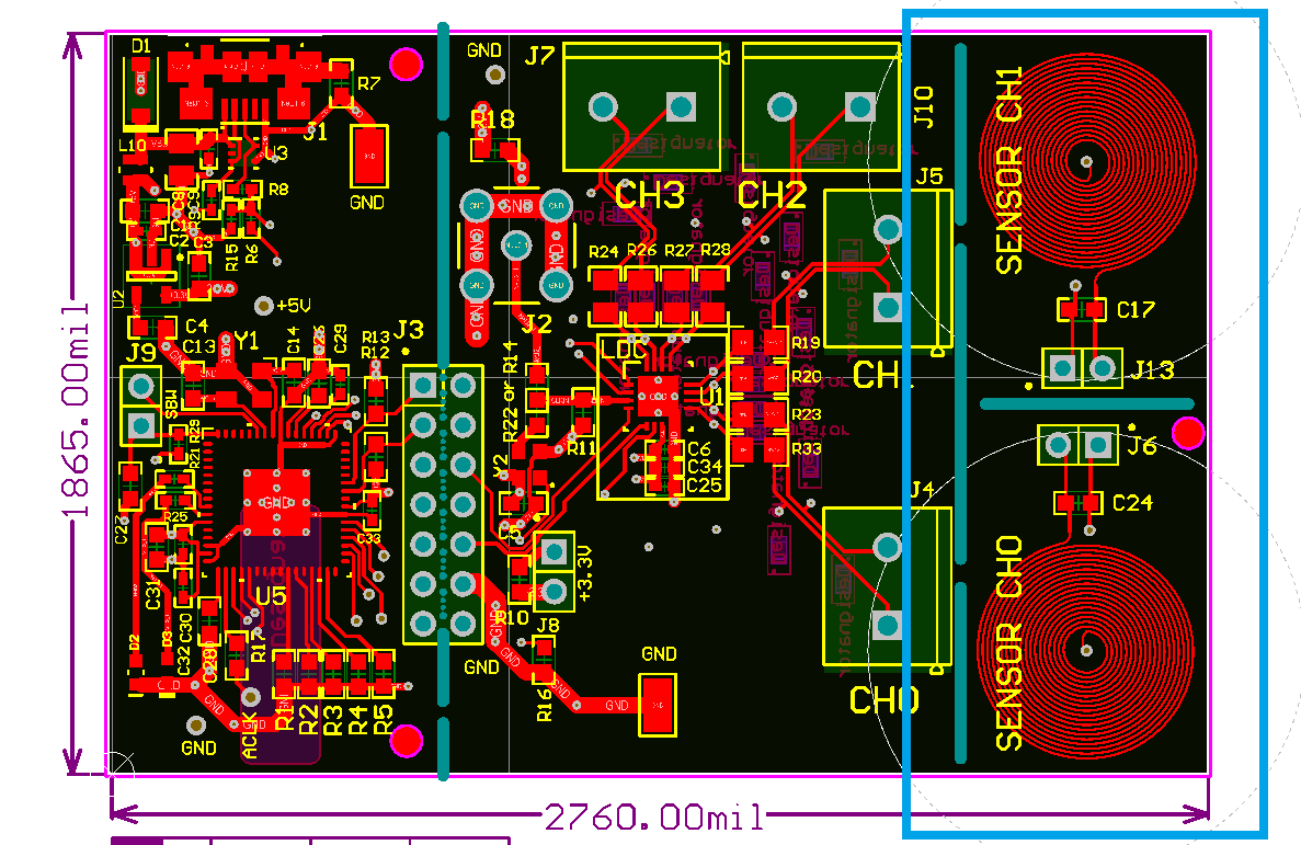
3. Does the input adjusment (Fin) always set to 1? Should I put the inductance value of the coil or just put 0? What is the inductance value of the evm coil? What "Input Deglitch Filter" should i set if i use

    the evm coil?

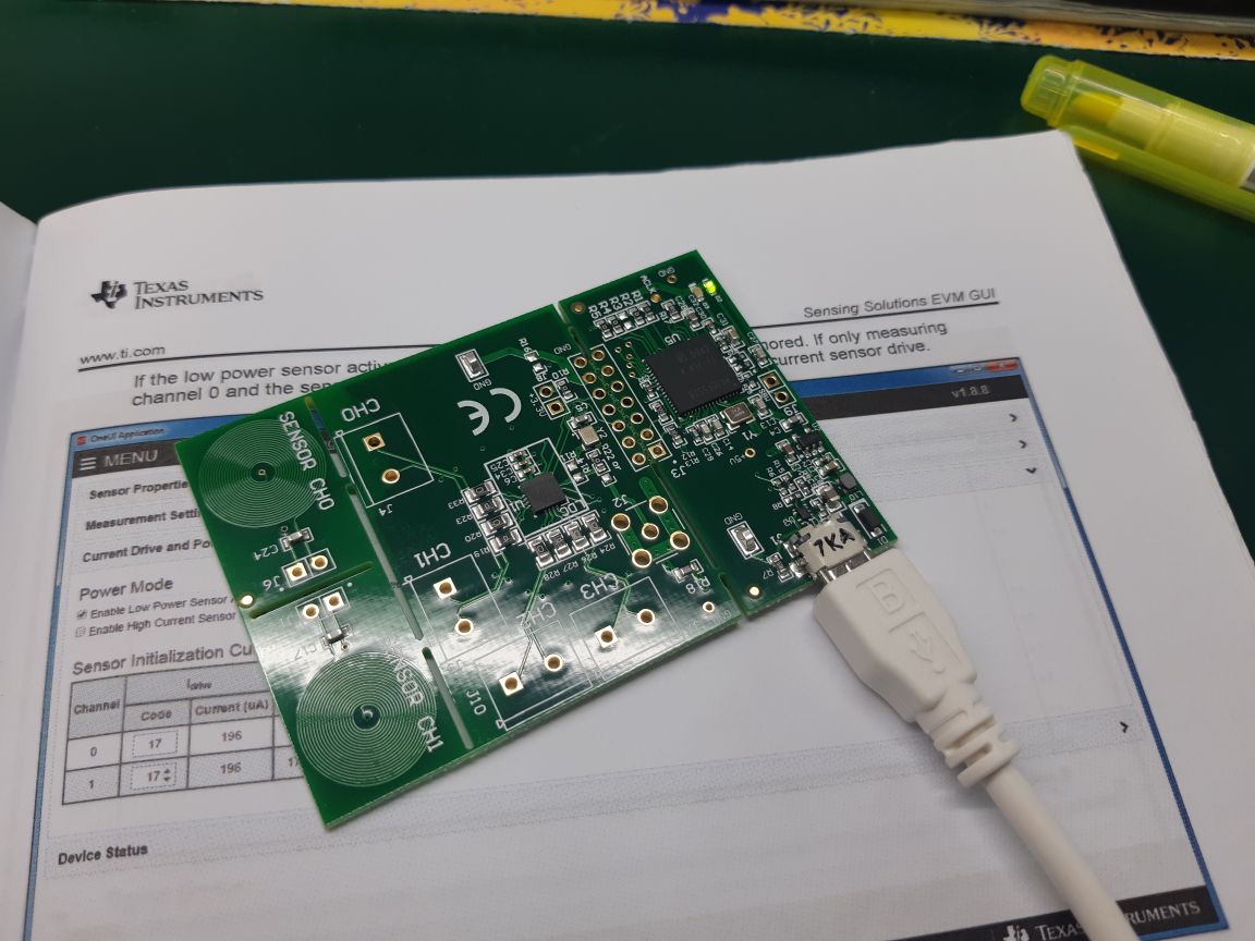
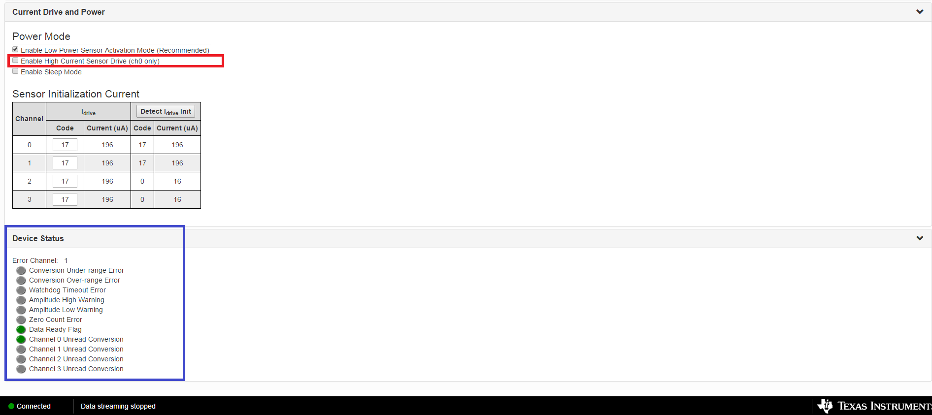
4. How about if I only choose channel 3, should i enable the "High Current Sensor Drive"? Please help me understand what are these in the " Device Status". What does it mean by this " Error Channel: 1"?

    What is this green light ndicate for?

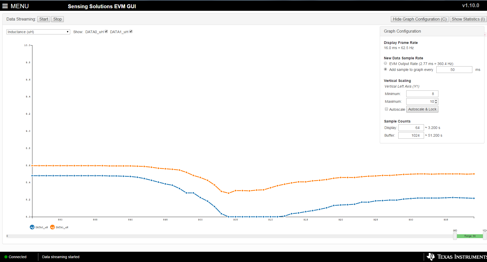
5. In the data streaming, why the graph goes downward instead of upward when i close the target to sensor coil?

  • Hi Janine,
    I've got your request. I will get back to you tomorrow.

    Best Regards,
    Bala Ravi
  • Thank you.
  • Hi Janine,
    Please find my answers below:

    1. "Repeat single channel measurement" is chosen when you are only measuring one channel repeatedly. And "Sequence channel measurement" is used when trying to measure multiple channels in a sequential manner.

    2. Reference count value is chosen based on the desired sample rate and necessary resolution. Max reference count means high resolution and high sample rate (measurement takes longer). Please refer to the following app note on how to optimize this: www.ti.com/.../snoa945.pdf. You can also refer to Section 8.2.4, Part 4 of the datasheet to determine how to calculate RCOUNT based on the convertion time.

    3. Yes, you can leave Fin as 1 and Series Inductance as 0. The coil inductance of the coil should be close to 32uH without a target. For "Input Deglitch Filter" set it higher such that the red indicator is not turned on.

    4. "Enable high current current sensor drive" setting is only channel 0. Please refer to the datasheet for more information on this. Device flag basically tells you what flags are triggered when running a measurement. You can again refer to the datasheet on what each flag means.

    5. When the target is taken close, the induced eddy's current will weaken the inductor's magnetic field which will lower the inductance. So that plot is correct.

    Best Regards,
    Bala Ravi

    Please click "This resolved my issue" button if this post answers your question
  • Dear Bala,

    What do you mean by "the coil inductance should be close to 32 uH without a target"?

    I am using an 8 layer coil with an inductance of 1000uH. And this is what it shows in the configuration. Without a target, this is the value.

  • Hi Janine,
    Ignore that statement, I wasn't aware you had your own coil. Yes, your inductance value makes sense.

    Best Regards,
    Bala Ravi
  • Ok Bala. Thank u.