This thread has been locked.

If you have a related question, please click the "Ask a related question" button in the top right corner. The newly created question will be automatically linked to this question.

IWR1443BOOST: phase discontinuity with mimo

Part Number: IWR1443BOOST

Hi Joe Quintal:

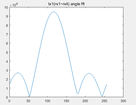
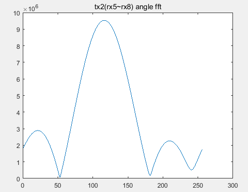
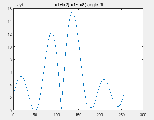
     we have the same question with "Santi Ortega" , about phase discontinuity on 1642 board in MIMO mode with the sdk demo program.

     the phase of tx1-(rx1~rx4) is discontinue with tx2-(rx5~rx8) and the  phase difference between the two sets(rx1~4 and rx5~8)  is

change with the target angle changing.  the original post is locked, we want to know have this problem been solved?

    thanks

  • Hi,

    I am not aware whether the previous problem has been solved. But I have done quite some antenna calibration and angle estimation myself. 

    To start with on IWR1443BOOST, the antenna pattern TX1-(RX1~RX4) and TX3 - (RX1~RX4) should be continuous (instead of total 8 visual antenna from TX1 and TX2 listed in your message).

    We would expect a continuous phase among these 8 antennas.  If not, we would expect a continuous phase after applying the phase/gain calibration.    When you do phase/gain calibration, you need to be really careful about the setup.   Basically, there should be a single strong target at 0 degree at azimuth direction.  The target should be the only target in the nearby range.  If you are using a corner reflector, it needs to be big enough to get enough SNR and be placed far enough to assume it is a point target.  

    Sometimes, it is hard to get the target placed at exactly 0 degree during calibration time, then your phase estimation will introduce a bias.  In that case, when you look at your DOA spectrum, you should still see an improvement on the DOA spectrum, i.e., the side lobe is much lower.    Depend on how clean is your setup, you may not see perfect phase, but I would expect some improvement.

    If you have done all these procedure, and still did not see the improvement on the DOA spectrum.  Please provide us the results and plot to get further help from us.

    Best,

    Zigang

  • hi zigang yang
       thanks for your suggestion about phase compensation.
       before we find the discontinuity, we have compensate the phase diff between RX channels using reflecter and darkroom.
        as i see,the phase difference between the two sets (rx1~4,rx5~8)is random, it may not caused by the rx channel.
       so we can not use some compensation value to solve this problem.
       actually, the compensation between rx channel has no improvement to this phenomenon.
       you can see the original question post by other user, and the diaogue between them, i have the just same question.
      my test data below:
    1.reflector at 8 degree:
    phase value:
    |rx(1):-1.2071|rx(2):-1.4856|rx(3):-1.7811|rx(4):-2.1569|rx(5):0.1620|rx(6):-0.2140|rx(7):-0.3995|rx(8):-0.8121
    2.reflector at 9 degree:
      phase value:|rx(1):3.0557|rx(2):2.7138|rx(3):2.3660|rx(4):1.9513|rx(5):-1.7020|rx(6):-2.1254|rx(7):-2.3571|rx(8):-2.8637
      when we use r1~r4 or r5~r8 angle fft separately,the dbf can give right and the same peak. but when we combine the two sets for 8 rx angle fft
      the dbf goes wrong. so it's not caused by the rx channel phase diff.
      Also, we can see the two sets phase difference is changed when the reflector from 8 degree to 9 degree.So we guess phase mismatch between two
      TXs due to board routing can not explain this phenomenon. beacuse the phase diff is not stastic.
  • HI,

    First, can you check whether you are using (TX1 and TX2), or (TX1 and TX3).  Because TX1 and TX3 should be used in IWR1443Boost to form 8 element linear antenna array.  

    Second, can you send me the complex values (DOA input) instead of phase information for your two test cases? 

    Best,

    Zigang

  • HI,

    Based on your complex data.  I did some calibration based on the first set of data (8 degree), and then used it for your second set of data (9 degree).  The code is listed at the end. And here is the result after compensation.  So, the peak is located at 6 degree for both 8 degree and 9 degree cases.   So, it is not perfect different by 1 degree.  But I would say phase estimation error at several degrees is normal.   I may also agree that a simple phase compensation between TX1 and TX2 maybe be enough, there maybe other leakages from RX1 to RX2 and etc.   But I would say if the angle estimation error is within several degrees cross angles, it is acceptable, and that is what we see as well. 

    The MATLAB code is attached here:

    a = [874325 - 2296796i
    205170 - 2403574i
    -472478 - 2213569i
    -1294669 - 1950097i
    2513575 + 410691i
    2257925 - 490783i
    2293441 - 968409i
    1510409 - 1593431i].';

    angleDelta = mean(angle(a(6:8)./a(5:7)));

    jump1 = angle(a(5) / (a(4)*exp(1j*angleDelta)));
    b = [a(1:4), a(5:8)*exp(-1j*jump1)];
    a1=exp(-1j*pi*((0:7).'*sin((-90:90)*pi/180)));
    figure; plot(-90:90, abs(b*a1).^2)

    a = [-2387530 + 205527i
    -2014882 + 918611i
    -1605891 + 1574635i
    -815417 + 2038463i
    -317777 - 2407704i
    -1266327 - 2044338i
    -1622046 - 1619236i    
    -2134822 - 609021i].';
    b = [a(1:4), a(5:8)*exp(-1j*jump1)]
    grid
    hold on; plot(-90:90, abs(b*a1).^2,'r')

  • hi zigang Yang
       i should give you the whole test data yesterday, 8 and 9 degree data can not describe the problem.
       i attanch the whole data from 0degree to 9degree for you to help us to analyze.
       In the doc, jump1 has been calculated in your way. jump1 value is increased with the reflecter angle increase.
       jump1 is changed regularly.but i have no idea to explain this phenomenon yet.
       the original post has been locked , i think may be the problem has been solved by your collegue.


    ------------------ 原始邮件 ------------------
    发件人: "zigang Yang"<bounce-44611@mail.e2e.ti.com>;
    发送时间: 2019年3月7日(星期四) 凌晨5:36
    收件人: "mmwave_sensors_forum"<mmwave_sensors_forum@mail.e2e.ti.com>;
    主题: Sensors forum: IWR1443BOOST: phase discontinuity with mimo


    A Message from the TI E2E™ Community


    zigang Yang replied to IWR1443BOOST: phase discontinuity with mimo.

    HI,

    Based on your complex data.  I did some calibration based on the first set of data (8 degree), and then used it for your second set of data (9 degree).  The code is listed at the end. And here is the result after compensation.  So, the peak is located at 6 degree for both 8 degree and 9 degree cases.   So, it is not perfect different by 1 degree.  But I would say phase estimation error at several degrees is normal.   I may also agree that a simple phase compensation between TX1 and TX2 maybe be enough, there maybe other leakages from RX1 to RX2 and etc.   But I would say if the angle estimation error is within several degrees cross angles, it is acceptable, and that is what we see as well. 

    The MATLAB code is attached here:

    a = [874325 - 2296796i
    205170 - 2403574i
    -472478 - 2213569i
    -1294669 - 1950097i
    2513575 + 410691i
    2257925 - 490783i
    2293441 - 968409i
    1510409 - 1593431i].';

    angleDelta = mean(angle(a(6:8)./a(5:7)));

    jump1 = angle(a(5) / (a(4)*exp(1j*angleDelta)));
    b = [a(1:4), a(5:8)*exp(-1j*jump1)];
    a1=exp(-1j*pi*((0:7).'*sin((-90:90)*pi/180)));
    figure; plot(-90:90, abs(b*a1).^2)

    a = [-2387530 + 205527i
    -2014882 + 918611i
    -1605891 + 1574635i
    -815417 + 2038463i
    -317777 - 2407704i
    -1266327 - 2044338i
    -1622046 - 1619236i    
    -2134822 - 609021i].';
    b = [a(1:4), a(5:8)*exp(-1j*jump1)]
    grid
    hold on; plot(-90:90, abs(b*a1).^2,'r')


    You received this notification because you subscribed to the forum.  To unsubscribe from only this thread, go here.

    Flag this post as spam/abuse.

    refid:9797893b-686b-42b9-aed3-e1cbad1dbd55

  • You are right. Your DOA input does look bad. Can you describe the test setup and how you get these DOA input?

    Best,
    Zigang
  • HI,

    Since I did not hear back from you, I will close this thread. Feel free to open a new one.

    Best,
    Zigang
  • hi
      sorry for my late for response. we have found some bug in our code bring to this problem.the TXs enable sequence is inverted,so the two sets of rx is jump.but the mimo configuration is the demo code.we just exchange the TXs enable order in chirp0 and chirp1 to solve this problem.this phenomenon disappear.i think this thread shall be closed.thanks for your highly effective support.
      if i have other question about mimo, should i create a new thread or just send the emal to you? 

    ------------------ 原始邮件 ------------------
    发件人: "zigang Yang"<bounce-44611@mail.e2e.ti.com>;
    发送时间: 2019年3月14日(星期四) 凌晨3:14
    收件人: "mmwave_sensors_forum"<mmwave_sensors_forum@mail.e2e.ti.com>;
    主题: Sensors forum: IWR1443BOOST: phase discontinuity with mimo


    A Message from the TI E2E™ Community


    zigang Yang replied to IWR1443BOOST: phase discontinuity with mimo.

    HI,

    Since I did not hear back from you, I will close this thread. Feel free to open a new one.

    Best,
    Zigang


    You received this notification because you subscribed to the forum.  To unsubscribe from only this thread, go here.

    Flag this post as spam/abuse.

    refid:5aaac9bb-68ec-4350-8751-be27a8a8e49c

  • HI,

    Glad to know that you have resolved the problem. Please open a new thread if you have other problems.

    Best,
    Zigang