This thread has been locked.

If you have a related question, please click the "Ask a related question" button in the top right corner. The newly created question will be automatically linked to this question.

IWR6843ISK: Heat sinking between antenna module and mmWaveICBoost carrier

Part Number: IWR6843ISK
Other Parts Discussed in Thread: MMWAVEICBOOST, UNIFLASH

Dear experts,

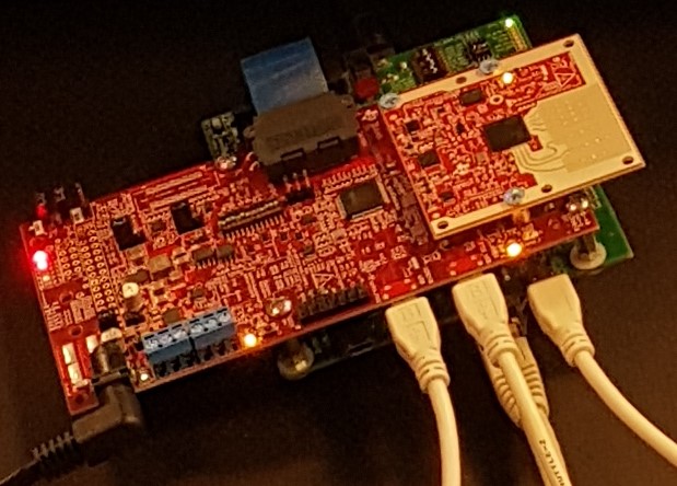
is it safe to connect heat-sinks on the antenna module and the carrier board? The manual (swru546a) recommends to do so, and I did, and the antenna module stopped working on a second day of experiments.       The "power good" LED turned off, the radar chip became very hot and died, probably due to electrostatic discharge when I was touching the heatsink. The carrier board remained operational. Now I want to minimize risks setting up a new module. Thanks.

Best regards, Timofey

  • Hi,

    What do you mean stop working? can you please provide some details.
    Also when addding the screws for heat sinks ensure the plastic washer are placed such that you are not shorting any path on the board.
    Lastly to use DCA you need to use the FTDI on the DCA1000 and disconnect that one the MMWAVEICBOOST.

    Regards,
    Charles O
  • Hello,

    for sure I double checked the PCBs around those holes for screws and to avoid any shorting I placed a plastic washer on the right side of the mmWaveICBoost. On the left side the heat sink was wide enough. Firstly I tested the kit in a stand-alone mode using a mm-wave demo which went well. Then I connected the DCA1000, configured the mmWaveICBoost and perfromed a few raw data acquisitions in mm-Wave Studio v.2 successfully. The FDTI on the mmWaveICBoost was disconnected from an USB port on a PC in the picture given above. On the next day I started to configure the kit from mm-Wave Studio again and during the firmware download the procedure got frozen. I restarted the kit and mm-Wave Studio all over again but the XDS debugger / COM port disappeared from Device Manager. The LED "PGood" on the antenna module went off, and all further manipulations did not help recover the module. I also noticed that the area around the radar chip became very hot. I switched the kit off, removed the screws between the module and carrier, and tried to start a mm-wave demo but Uniflash couldn't detect the radar anymore. By the way the antenna module without those heat conducting screws was decently cold when the power was on, "PGood" was off. Certainly I took care of SOP jumpers and switches while working with the kit in different modes.Any idea what went wrong?

    Thanks,

    Timofey       

  • Hi,

    • Does the XDS110 interface come back up when you place a different antenna board on the MMWAVEICBOOST?
    • What duty cycle were you running on and for how long?
    • What is the voltage and current ratings of the power supply used 
    • Have you tried troubleshooting the antenna board? Are the voltage output on the PMIC voltage rails, supply input and and voltage nodes on the device expected level?

    Regards,

    Charles O

  • Hello Charles,

    herewith my point-to-point answers:

    1) yes, the XDS110 comes back with a new antenna module.

    2) not greater than 22%, I was running a DataCaptureDemo_xWR.lua with its own settings. In fact the demo crashed during the firmware download.

    3) 5V / 2.5A.

    4) we found out that PMIC 1V24 is not OK (low) which means no supply to LDO at U5 for PGood. More specifically, the voltages were measured as follows 

    TP2  0.0V faulty

    TP3  0.8V faulty

    TP4  0.68V faulty

    TP5  0.59V faulty

    TP6  0.68V faulty

    TP7  0.68V  faulty

    C45  3.3V  OK

    C40  1.8V  OK       (PMIC1V8)

    C47  0.0V  faulty   (PMIC1V24)

    C5    1.8V  OK

    C18  0.02V  faulty

    C22  0.02V  faulty

    C26  0.0V  faulty

    Hope this helps. 

    BR

    Tim

  • Hi,

    Please share a screen shot of the interface of the crash while loading the firmware.

    At this point I will also recommended continuing the test with the other board while we debug this issue. Please ensure the heat sinks are placed such no shorts are created on the board.


    Regards,
    Charles O

  • OK, thanks!

    Then I will connect the heat sinks on the left side only where metallization is pretty wide on both boards.

    No screenshot, sorry, no wish to replicate the damage... It's easy to imagine frozen progress bars in mmWave Studio and Uniflash.

    BR

    Tim 

  • HI,

    Wanted to see the other information on the mmWave Studio interface, a few others have confirm situations where the SOP is not latching to the right value.

    Regards,
    Charles O
  • Hello,

    understood. I replicated the experiment with a good antenna module carefully. When I connect the evalkit in mmWaveStudio and run the data capture demo for the first time, then everything goes smoothly and the demo after a while returns a Matlab figure with signals. But when I run the demo once again in the same environment it gets frozen during the MSS download. At this point the problem began with the damaged antenna module as I recall... Now I turned off the evalkit, terminated mmWave Studio from Task Manager, restarted everything and ran the demo smoothly again but only one time. See screenshots below. By the way note a duty cycle of 51,2% now, my previous estimate of 22% was based on one Tx and 0 idle time. 

    Looking forward to your conclusion. 

    BR

    Tim

  • Hi,

    You don't have to reload the firmware everytime you want to run a capture, you only need to do this after shutting down mmWave studio, in this case you also need to reset the DCA1000. Did you try doing this on the "broken" antenna board also?
    To run a second capture the steps on the connection page/tab is not required.


    Regards,
    Charles O
  • It's clear. The older antenna board became damaged after that point of the frozen firmware download followed by other manipulations. Now it does not show up in the system at all, or do you still want a screenshot with it?

    BR
    Tim
  • No the screenshot is not needed.
    Just keep in mind running a second capture does not require re-connecting the UART and SPI

    Regards,
    Charles O