This thread has been locked.

If you have a related question, please click the "Ask a related question" button in the top right corner. The newly created question will be automatically linked to this question.

LMP91002: LMP91001/2 with N02 SGX sensors

Part Number: LMP91002
Other Parts Discussed in Thread: LMP91000

HI 

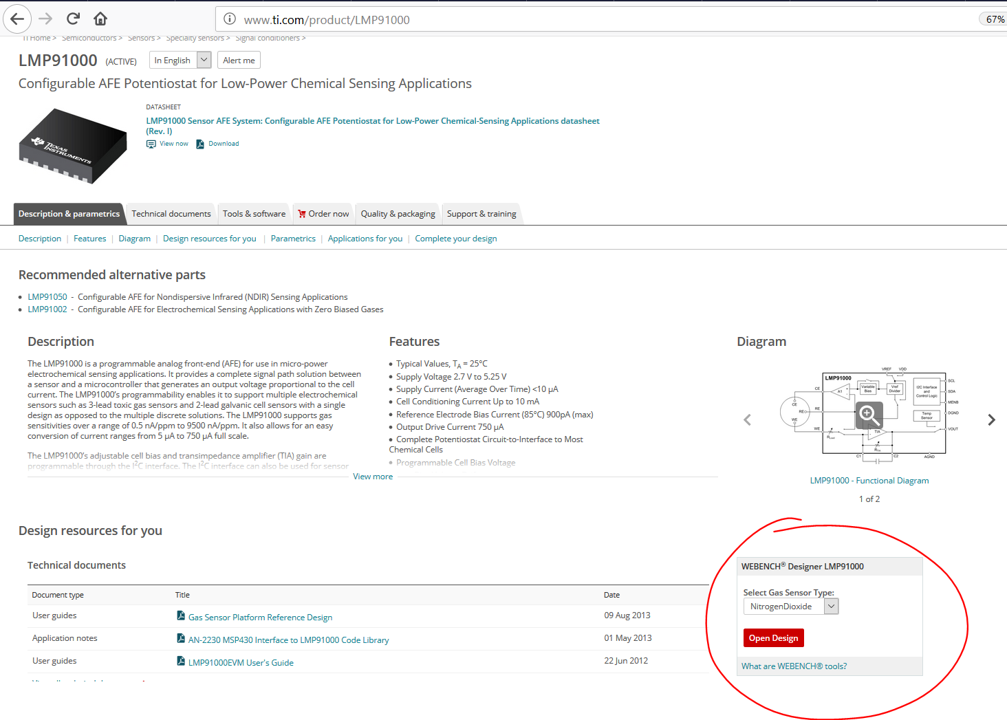
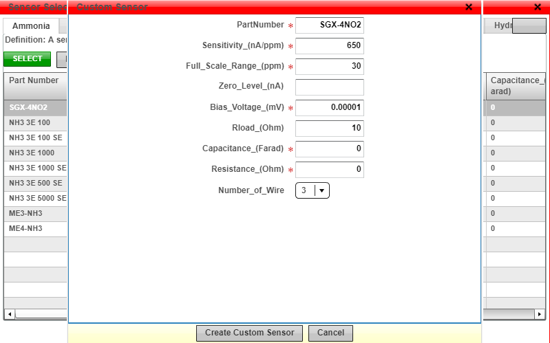
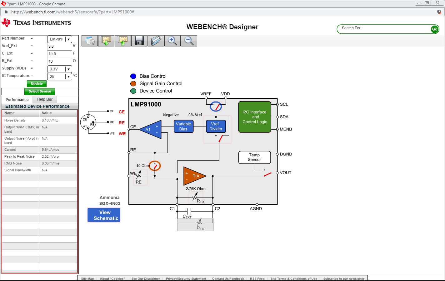
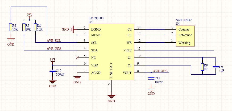
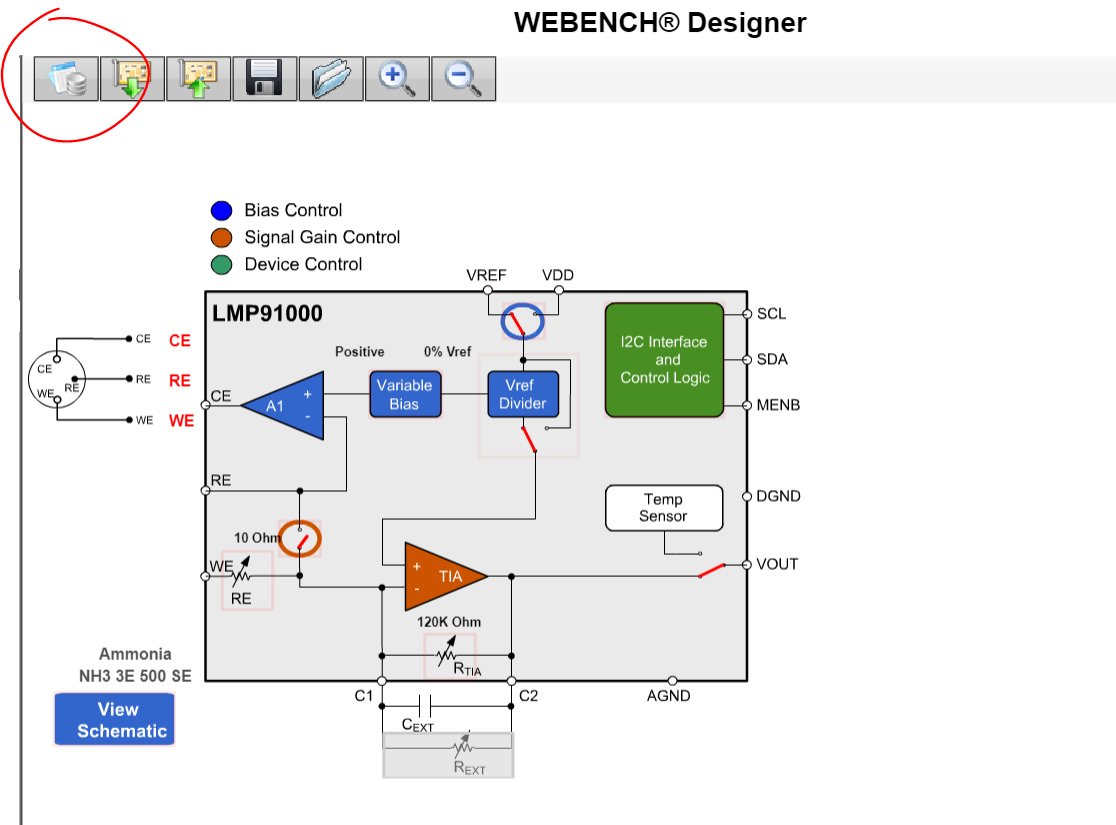
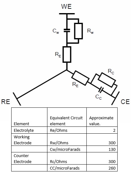
I am very interested in using either LMP91001 or LMP91002 , for the following sensor SGX-4NO2 . The pdf is attached,

Can you please advice me if these sensor device ic will be compatible with this sensor?

What is the difference between LMP91001 and LMP91002 ? or if there is any other device we could consider?

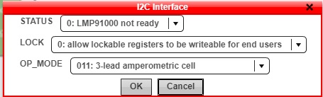
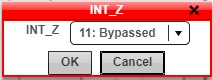
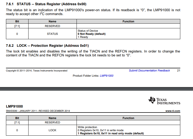
We are looking into a plug and play design for this sensor, so we do not want to spend much time experimenting around as this is not a priority sensor, so please do advice how the device must be configured.

Thank You

DS-0228 (SGX-4NO2) V1.pdf

  • Hi Dharmesh,

    I'll get back with you shortly.

    Jalen
  • Dharmesh,

    The LMP91000 is another device that you should consider, and has more support for. The only difference between the LMP91002 and LMP91000 is the operating voltage and configuration when attaching the cell sensor itself.

    Looking at the pdf you provided, both parts should be compatible with the sensor.

    For additional design assistance, please utilize our WEBENCH tool, which can be found on the product folder page as shown below.

    Jalen

  • Hi Jalen

    Thank you for your reply, sorry for my late reply.

    I have attached the datasheet for my sensor, please advice me if i need any further information to crate a sensors part on the WEBbench tool? I am new to using such sensor, and would need to some help in creating a new part in the tool with the information provided in the datasheet.

    So that i get a feel of this tool, i have selected a random sensor(N02-A1) from the list, but is there a guide on how to progress foward in the tool? Do you offer a screen share support?

    0652.DS-0228 (SGX-4NO2) V1.pdf


  • Anyone who can help me get started?

  • Hi Dharmesh,

    There is an interactive tour pop up when you open up the tool, have you used that? It will help you to progress further in the tool.

    As far creating a new sensor, here is what I've done to get you started (this is information from the datasheet you provided). If you have information about the resistive/capacitive elements of the sensor, please include that as well.

    Jalen

  • Dear Jalen 

    Thank You for your reply.

    I will contact the sensor manufacture if there is more information on the Capacitance and resistance.

    I have managed to create the custom sensor as shown below. I am going the the steps from 1 to 9.

    1. I select my sensor.

    2. "Modes of operation"- As shown below: What is the difference in status and lock options?

    3. "External Reference"- I have kept to use a the internal Vref, which i believe will be VDD 3.3V(output of the LDO). Am i correct in saying that Vref should be 3.3V as my ADC is 3.3

    4."VREF Devider" As my Vref is going to be 3.3V, it does not need to be divided as my ADC will read 3.3V, therefore the setting will be in bypass mode as shown below. Is this correct?

    5."Variable Bias", As per extra information from the following attached PDF, it seems that the SGX-4N02 output bias is negative, but what should BIAS be set to?

    6. How do i determine that correct TIA GAIN for the sensor?

    7. How do i determine that correct RLOAD the sensor?

    8. Is shorting FET required?

    With exception of points 6-8. i have added as much information as possible and kept the defaults for point 6-8. I now come the following screen.  What must i do next, as its not very clear?

    What i aim to achieve is the setting for i2C, so that device simply output an Voltage that my ADC can continuously read to determine N02 levels in the air. Am i correct in believing that is what this device will help me achieve?

    I have also attached my schematic below. It looks fairly simple, but do i need to set R9 and C9 to particular values for this sensor?

    DAS768835AA-ECVQ-EK3-User-Guide-V4.pdf

  • Hi Dharmesh,

    I will address your questions below:

    2.


    The register maps are explained in the LMP91000 Datasheet please take a look for additional help.  

    3. Yes, this would be the correct setting. 

    4. Correct.

    5.  This setting is correct. 

    6. The TIA gain will convert the small currents from your electrical cell to useful voltages for measurements in your ADC. The recommended load resistor for your sensor is 10 Ohms (this can be selected in the WEBENCH tool). So please determine what system sensitivity you would need for your ADC and choose the proper RTIA for your application. 

    7. 10 Ohms, refer to point 6. 

    8. This is not recommended.

    From what I can tell the output of the LMP91000 is going to be what you need, so this device will help in your application. 

    Pins C1 and C2 can be used to attach in external resistor if different gains are required, otherwise keep this resistor (R9) and capacitor (C9) unpopulated.

    For additional help in your design, please reference this application note for your sensor as well as this TI reference design that uses the LMP91000.  Both these documents have plenty of information to help clear up your questions.

    Jalen

  • HI Jalen

    I will read the documents and update you on any query.

    I will also update my schmaticso that Vref is also 3.3V.

    What i wanted to ask was ,does the tool also produce  a list of register or what i need to do in terms of i2c?

    When you say " So please determine what system sensitivity you would need for your ADC and choose the proper RTIA for your application. " what does this refer to ? I am using an Atmel AVR ADC. IS there certain parameters i need to look out for?

    Thanks

  • Dahrmesh,

    Yes, there is a Register Map icon above the block diagram that along with reading the datasheet should help you with the register map.

    As mentioned, please take time to read through the datasheet and application note I provided in my previous post. These explain your questions pretty well.

    Jalen

  • Hi Jalen

    In regards to your first post, about "if you have information about the resistive/capacitive elements of the sensor", i have been sent the following. Which values from the image would i need to add into tools parameter.

    Thanks

  • Dharmesh,

    It should be fine to leave those values as 0.

    Jalen
  • Hi Jalen 

    Great, Thanks.

    I have started working on the layout. The datasheet mentions it best to keep the sensor away from high frequency, which i am. But my looking at the reference design, it seems that LMP9100 device was kept underneath the sensor. My Sensor does not have any clearance below it, therefore i have kept the ic on the side, with a ground pour around all the traces. Does it look ok? Or should it be underneath it?

    Thanks

  • Dharmesh,

    It is recommended to have the LMP91000 device underneath the gas sensor as a technique to reduce the length of traces. Be sure to have your sensor and device close to each other as well as far from high frequency signals.

    Jalen
  • Thanks

    Unfortunately could not place it below, but close as possible. 

    Is there away to test if LMP91000 is setup correctly without the sensor? e,g, placing a resistor between two points etc. I presume to fully test it i need to be in the environment i am hoping to test?

    If i want to find what the ADC reading equals to in terms of ppm, do i need to ask the manufacture or is standard formula? 

    Regards

  • Dharmesh,

    Yes you will need to be in the environment you are hoping to test to verify operation of LMP91000. 

    Is your question here how to make sure the ADC can read the sensitivity of the output of LMP device?

    Jalen

  • Yes i would like to insure LMP device is able to output properly(set correctly) for my ADC to read it. Would like to avoid be exposed to what i am trying to test as well.

  • Dharmesh,

    You need to be sure that the LSB (least significant bit) of your ADC can is smaller than the system sensitivity. The LSB is the smallest signal that the ADC can convert. If your sensor sensitivity is smaller than the LSB, then your ADC will be unable to detect the incremental output voltage per ppm.

    For example,

    The TIA has a gain of RTIA for 3-lead Amperometric Cell mode. (this is where selection of  RTIA comes into play)

    Your sensor gain is 600 nA/ppm or 6 x 10⁻⁷

    If your gain is 14 x 104 then your system sensitivity becomes (6 x 10⁻⁷ )x (14 x 104 ) = 84 mV/ppm.

    Your LSB for ADC needs to be greater than this number.

    Hope this helps,

    Jalen

  • Hi Jalen

    My ADC is 10-bit adc that comes with my uC. 

    So if i am correct the LSB will be: 3.3/1023, =0.0032V, therefore should be able to detected the voltage.

    What i was trying to ask was , is it possible to place the device in some form of test or simulation mode, just to insure everything with exception of the sensor is working correctly?

  • Dharmesh,

    One way you could check operation of LMP91000 is by reading the temperature sensor output from Vout pin. This would require setting the device in Temperature Measurement mode, which is explained in the datasheet.

    Have you checked out the LMP91000EVM ? It will help to evaluate the performance and operation of the LMP91000.

    Jalen
     

  • Dharmesh,

    I am going to go ahead and close this thread. If you end up having additional questions, feel free to create a new thread.

    Jalen