This thread has been locked.

If you have a related question, please click the "Ask a related question" button in the top right corner. The newly created question will be automatically linked to this question.

LDC1614: Coil design

Part Number: LDC1614

Dear Bala and Clancy

1. As you said, using another channel as a reference to rid the temperature drift. In our design, space is limited.

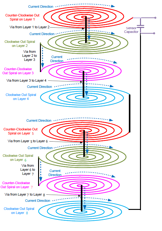
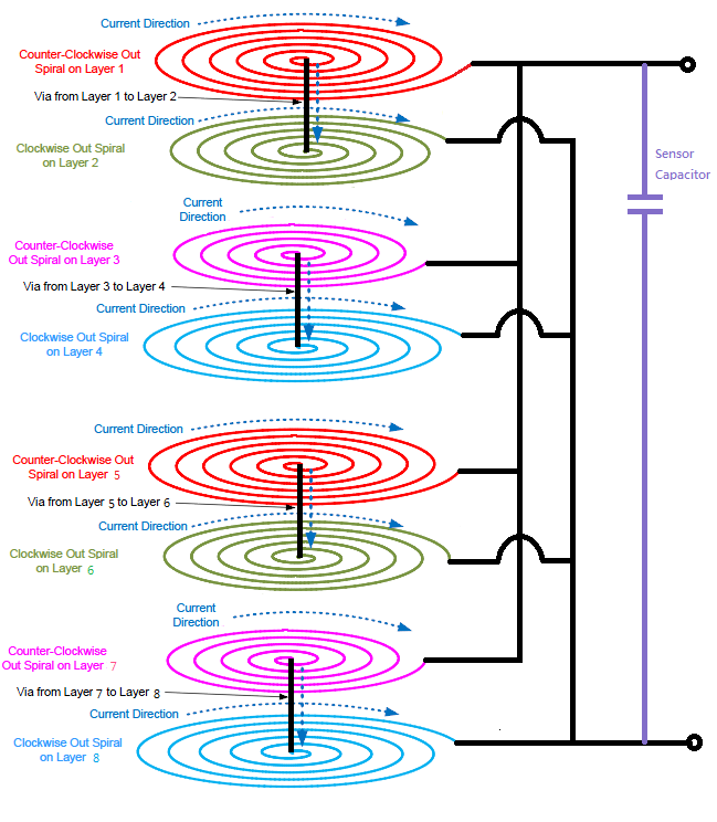
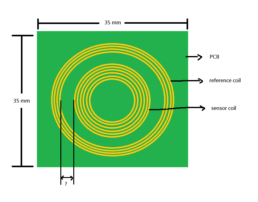
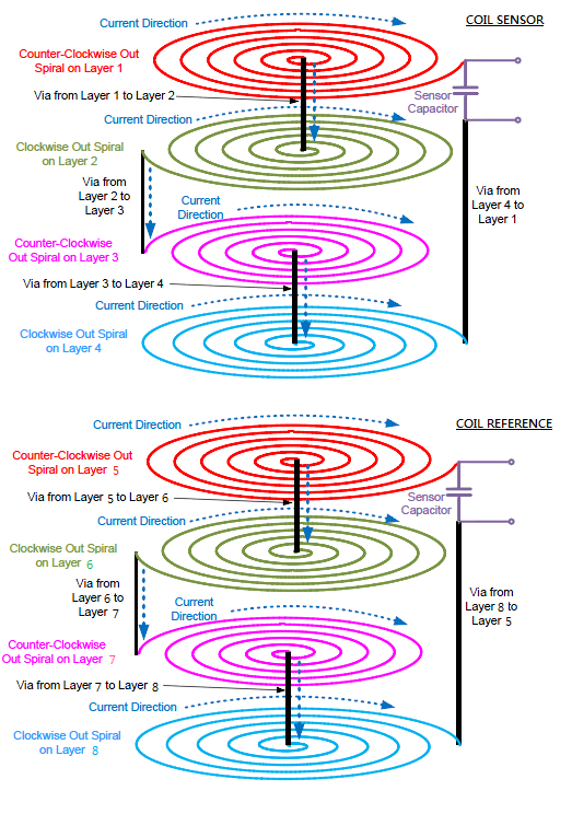
    Is it possible to design a coil (a sensor coil and reference coil) in 1 PCB (stacked form) for 2 channels? 1 to 4 layers is for coil sensor and 5 to 8 is for reference coil.

    If possible what is the required layer gap between layer 4 and layer 5.

    Please see figure below. 

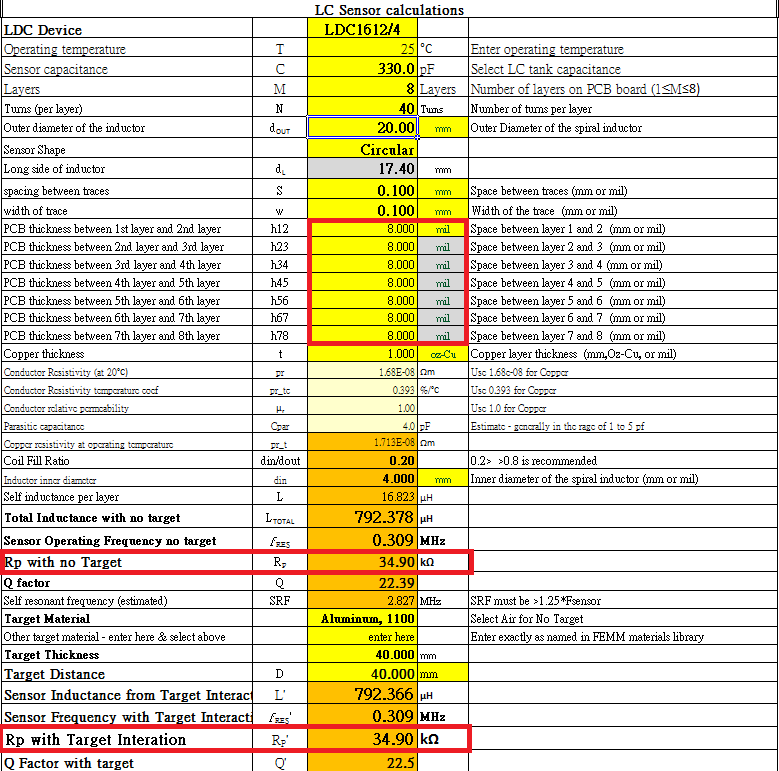
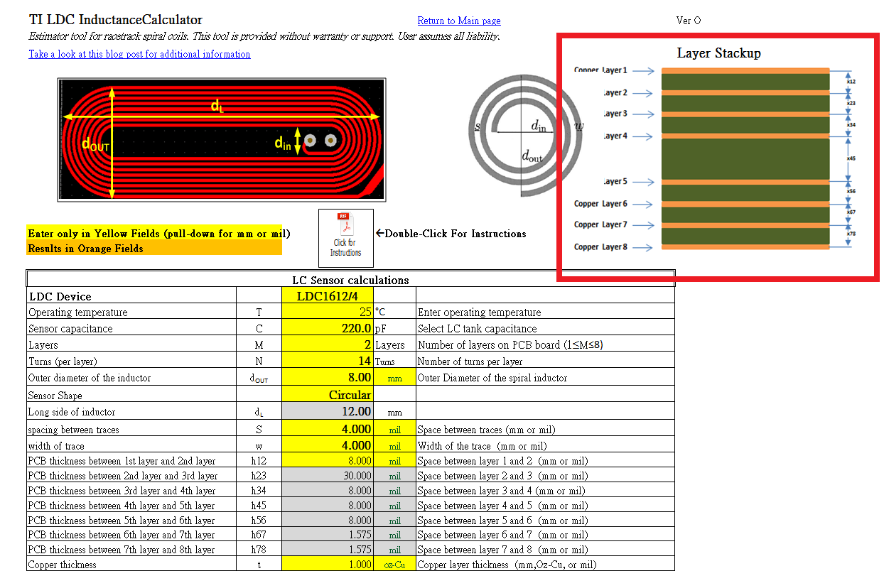
2. In designing coil, is it necessary to input the layer to layer gap value? Figure below is from LDC inductance calculator.

    What does it mean under layer stackup,  each layer value "x12, x23, x34...."?

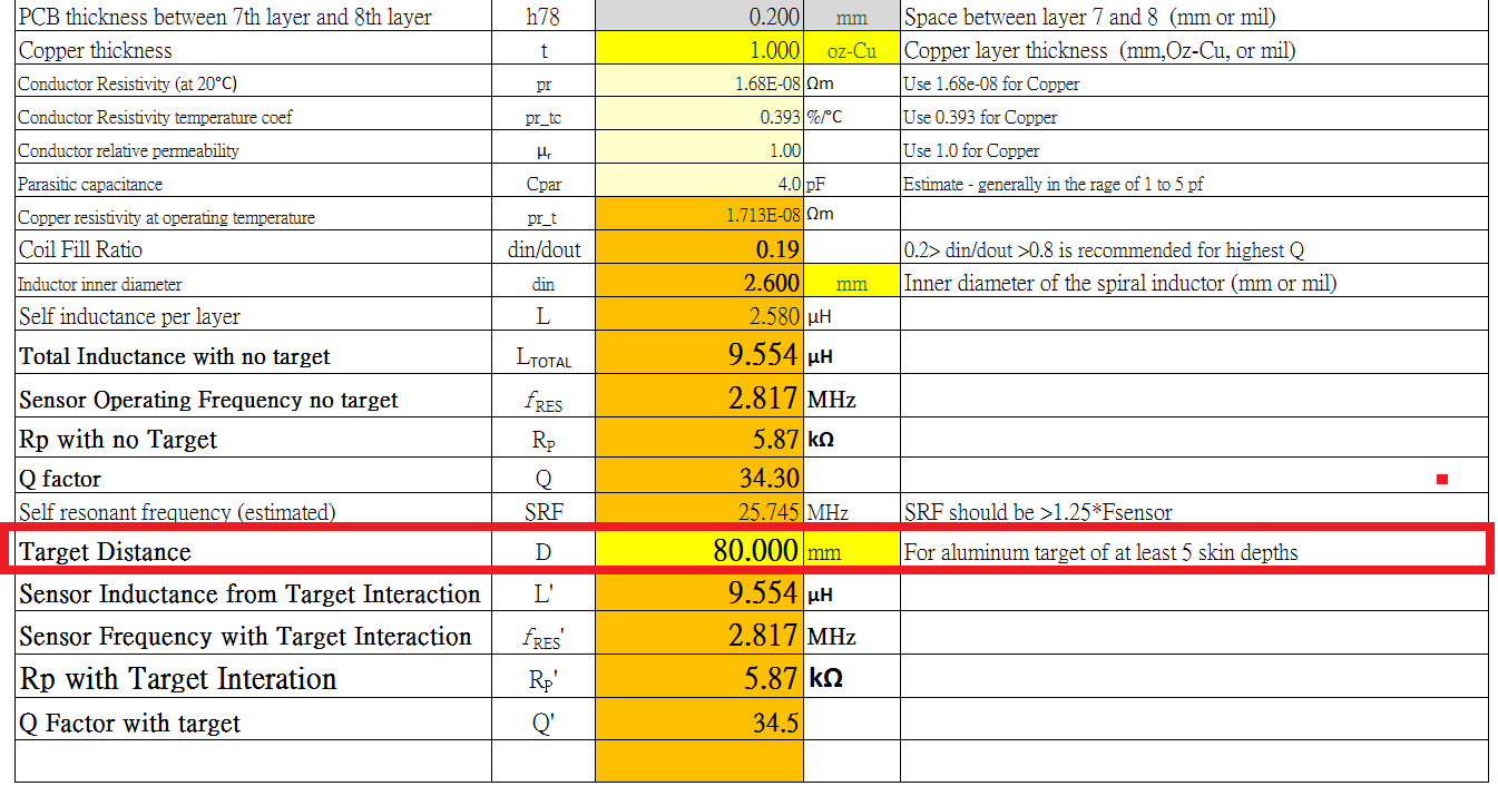
3. In LDC Inductance Calculator, is it possible to set the distance using 2 cm dimension of coil with 8 cm target distance?

  • Hi Janine,

    1. I would not recommend this approach for the LDC1614. This is because the LDC1614 uses a round-robin approach to measure each channel, and when a channel is not being measured it is grounded. With stacked coils, you would have one grounded coil directly above or below the coil being actively driven. The grounded coil would essentially act like an additional target and would severely decrease the sensing range of both coils.

    2. It's not necessary to input this information. The calculator tool has default common values that work for most coils. If your stackup varies significantly from the default values, you may wish to change this information so the calculator tool's estimates are more accurate.

    Under Layer Stackup, "x12, x23, x34, etc" are the distances between each of the copper layers. "x12" is the distance between copper layer 1 and layer 2. The values correspond to "h12, h23, h34, etc" in the LC Sensor Calculations section.

    3. This target distance is too large for a 2cm coil. The LDC161x devices can measure targets at distances of up to 200% of the coil's diameter, which would be 4cm in this case. The coil should be at least 4cm in diameter to measure a target 8cm away. The Excel Calculator Tool also includes a FEMM calculator tool (a separate tool in the same download folder), which I recommend using for this application. It will give you a more accurate measurement of your target's effect on the sensor coil.

    Best Regards,
  • Thank you Kristin.

    Here's my follow up question.

    1. What is the ideal trace width, trace to trace spacing and pcb board thickness for pcb sensor coil?

    2. Does the signal from the coil need to control the impedance? What is this Rs mean? Is it a resistor series to coil?

    3. I used the excel_FEMM calculator. I want to design a coil with a coil dimension of 20 mm, 0.1 mm trace width and 0.1 trace to trace spacing. Its  board thickness is 1.6mm including copper.

        Does the layer to layer pcb thickness value(in mil) is correct?  What is this Rp mean? Do i need to put a resistor parallel to LC tank the same value as shown below? Please figure below.


    4. Please help me understand what  is the difference if i use either series coil or parallel coil? Figure below from " LDC Sensor Design".

    5. In the application note, it only shows 4 layers, but for 8 layers inductor coil (Series), is this correct?

    6. If i use 8 layers inductor coil (Parallel), is this correct?

    7. How to determine if  Rs is too high or Rp is too low? How to minimize Rs? 

  • Hi Janine,

    I've answered your questions below:

    1. There's no ideal trace width/spacing or board; there are many different combinations that can yield a working coil for your application. The key parameters for the coils are the overall diameter (which determines the maximum sensing distance) and the coil's Rp (which determines how much drive current is required to keep the sensor oscillating). It's desirable to keep Rp high, and to do this you should minimize the coil's series resistance.

    2. Rs is the equivalent series resistance used to model both the losses in the coil itself and the losses in the eddy current generated in the target. It is not an additional discrete resistor in the sensor; it is intrinsic to the LC tank. I highly recommend reading section 1 of the LDC Sensor Design app note, which discusses both Rs and Rp in detail.

    3. If you click on the yellow box associated with h12 that currently says "mil" (at the top right corner of the red box in your picture), you have the option to enter values in mils or in mm. Changing the units in this box will change the units in all of the gray boxes below. You do not need to convert between mm and mils. As for your Rp question, please see section 1.2 of the LDC Sensor Design app note I mentioned above.

    4. Connecting the coils in parallel is one way to reduce Rs (which increases Rp). There is still significant mutual inductance between the coils, so the inductance is not reduced as much as the Rs. Figures 11 and 12 in that same section of LDC Sensor Design should clarify the different electrical models for the two coil layouts.

    5. As long as the current is always flowing in one direction (in this case always clockwise), this layout should be fine. However, generally no more than 4 layers are necessary to create a functional coil. I would not recommend an 8 layer coil unless it has an extremely small diameter.

    6. This layout should work for an 8-layer parallel coil, but again I do not think 8 layers are necessary.

    7. The minimum Rp that the LDC1614 can drive is 1kohm, which is specified in the electrical characteristics table of the datasheet. I would not worry about the actual value of Rs and instead focus on the Rp value in the calculator tool. You can use the equation in section 1.2 of LDC Sensor Design to guide how to increase Rp. In general, you can reduce the AC resistance of the coil or reduce the capacitance of the LC tank.

    Best Regards,
  • Dear Kristin

    Thank you for the clarification. I have another question. Due to the limited space, is it possible to design this kind of coil where the sensor coil and reference coil are in 1 PCB?

    If possible, what is the required distance between the two coils? Please see figure below. 

    If not possible, what would be the ideal position for the two coils? Thank you~

  • Hi Janine,

    This would not be possible for the LDC1614 either. The coil being measured would still view the other coil as a target. In addition, this layout would not make an effective reference sensor. The reference coil and the sensor coil should be as close to identical as possible so that any temperature changes affect both coils identically. The best reference and sensor coil layout is two identical coils side-by-side on the same PCB. The centers of the coils should be spaced a least one coil diameter apart.

    Best Regards,
  • Got it. Thanks Kristin.
  • Dear Kristin,


    You said 8 layers are not necessary. Does it mean, the value of coil inductance is not necessary to determine the sensing range? Is it the diameter of coil (dout)? I am using a coil diameter of 2 cm and our target sensing distance is 4 cm.
  • Hi Janine,

    That is correct: the coil's inductance does not affect the sensing range. The sensing distance for all LDC devices is based on the diameter of the sensor coil. The LDC1614 can detect targets at distances of at most 200% of the coil diameter. If you need to use a fast sample rate or you have a high noise floor, you may have difficulty sensing the target at 4cm using a 2cm coil.

    Best Regards,