A related question is a question created from another question. When the related question is created, it will be automatically linked to the original question.
If you have a related question, please click the "Ask a related question" button in the top right corner. The newly created question will be automatically linked to this question.
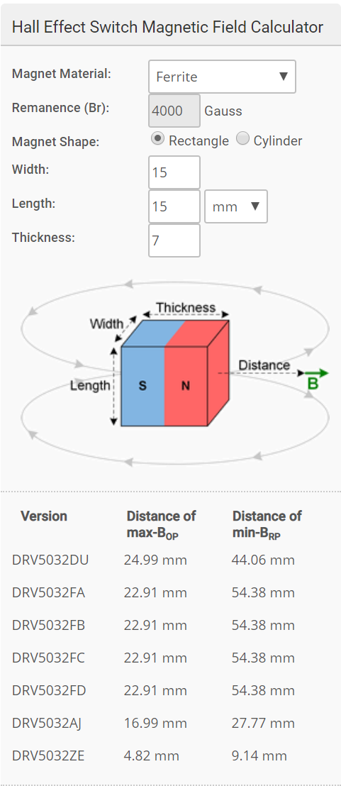
Thank you for using the TI forum. The magnetic field calculator for the DRV5032 is on the main product page (http://www.ti.com/product/DRV5032). It is on the right hand side, and you may have to scroll down a little bit. It looks like this:
If this answered your question, please click the green "This resolved my issue" button. Thanks!
I see what you are saying now. That feature is temporarily not on the DRV5032 page, but it is currently available on the DRV5055 product page (http://www.ti.com/product/DRV5055)
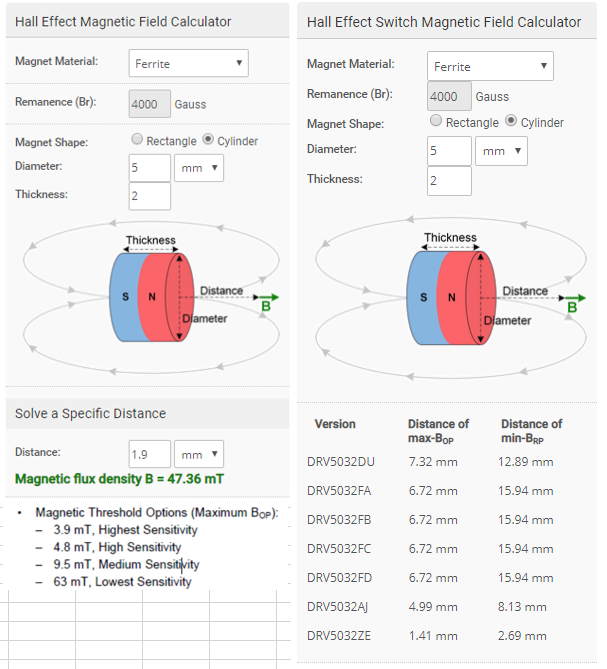
Yes, the AJ version operates at a maximum threshold of 9.5mT, and it looks like in your system there will be ≈47mT, which is more than enough to trip the sensor.
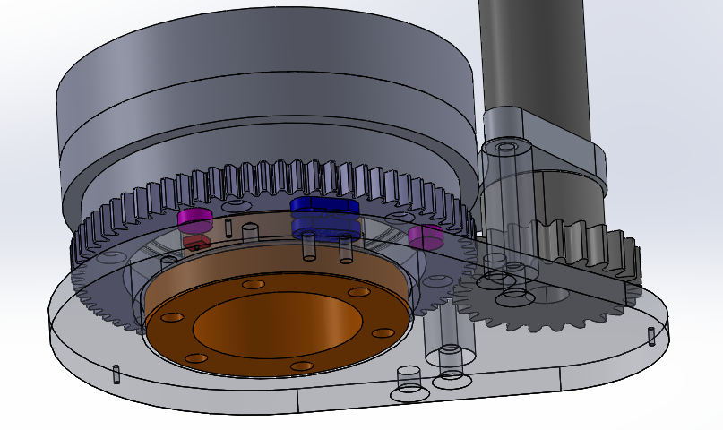
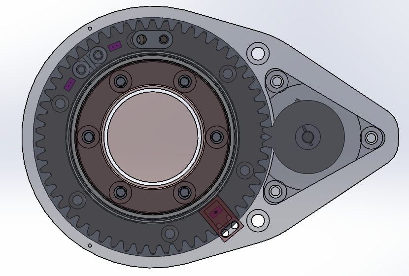
To answer your questions I will need some more specific information about your system. Do you have a block diagram of the mechanical structure that you can share with me? Also, I will need to know what you are trying to detect specifically. Meaning, I see that you want to know the angular position of the rotating disc, but what I don't know is what kind of accuracy you are looking for. Are you just trying to count rotations, or maybe you want know if the rotating disc is in one or two specific positions? This plus any other useful information can help me give you better recommendations.
Thank you for sending that information. Here are my answers to your questions:
Abel Girma said:
Do you anticipate any issue/interference from the metal to the magnetic flux.
Although the steel will affect the magnetic field, it looks like it the sensor should still work fine in this situation.
Abel Girma said:
Also how do we install the sensor on the metal and wire it?
If you are using a surface mount device (which it looks like you are), then you will need to find a way to get a PCB mounted to your aluminum plate with the sensors in the desired positions. Technically if you used a different sensor that comes in the TO-92 package, then you could put the PCB next to the system and bend the sensor into place, but the sensor you want does not come in that package.
If you would like to test out the sensor itself, you can order the HALL-ADAPTER-EVM (http://www.ti.com/tool/hall-adapter-evm) and request a part sample from the DRV5032 product page (http://www.ti.com/product/DRV5032/samplebuy). Note that currently the HALL-ADAPTER-EVM only supports the TO-92 and SOT-23 packages, so you would need request the SOT-23 version to test out.
Here are some ideas to help you improve/meet your accuracy:
1) With unipolar switches:
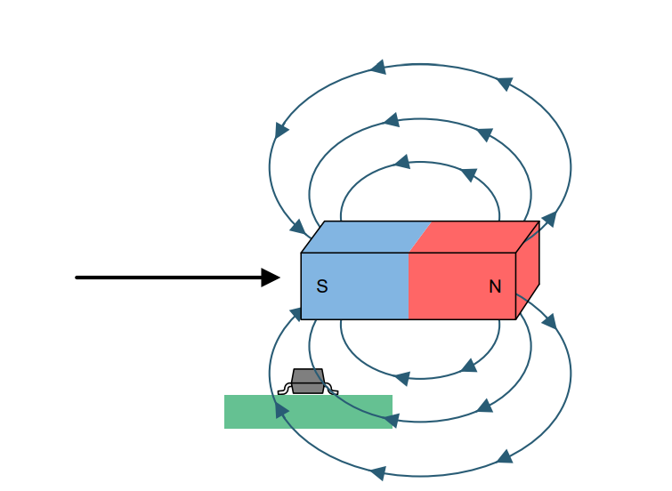
Using the switch method, you can use a unipolar switch and turn the magnet sideways (or use a diametric magnet) as in this image:
This will increase your positional switching accuracy as the magnet moves over the sensor (smaller magnet thickness = better positional accuracy). The reason for this is that when the magnet is directly over the sensor, the magnetic field is very close to zero (and the wrong magnetic field as the magnet approached the sensor). As the magnet starts to move past the midpoint, the magnetic field seen at the sensor increases until the edge of the magnet is directly over the sensor (as in the image above), which is where the field is strongest. As long as the strength of the magnet is strong enough to trip the sensor, then the sensor will be tripped somewhere in between when the center of the magnet and the edge of the magnet pass over the sensor. This means that the sorter the magnet, the tighter the positional tolerance.
It is important to note that this method works best when the magnet is only moving in one direction relative to the sensor. If the magnet is going to be moving in both directions, the you could potentially use a sensor like the DRV5032FD or DRV5032DU (X2SON package), which are unipolar switches that have a separate output for north and south magnetic fields. This way you could use one output when the magnet is moving in one direction and the other output when the magnet is moving in the other direction.
Technically, right when the exact center of the magnet is over the sensor, both outputs will be off (the width of this region depends on the magnet). This could let you know when you have reached the exact center, only you would need to add an additional sensor so that you can tell the difference between the magnet being exactly in the middle, and the magnet being completely absent.
2) With linear devices
Linear Hall devices, such as the DRV5055 or DRV5056 can also be used to achieve your desired accuracy, with calibration. There are two different approaches here:
A) You can have the magnet sideways as in the image above and use the DRV5055 (or DRV5056 if you want to ignore one magnetic pole). You can then move the device to the desired location and read the output of the sensor. This reading is then associated with the calibrated position. The magnet would need to be sideways to prevent the same output from appearing in two different physical locations. Also, at the desired location, the magnet would need to be near the sensor but not directly over it so that you don't get a zero magnetic field.
B) If you cannot turn the magnet sideways, then you can use two DRV5056s to increase your accuracy. For example, you could have one sensor to the left of the desired stopping location, and another sensor an equal distance to the right of the desired stopping location. Then your desired stopping location is when the two sensors have approximately the same output (calibration could also refine this method, and you would need to make sure the sensor output is not saturated)
I hope this helps give you some ideas of how to improve your system accuracy.
Is there a way for us to establish any heritage of flight (Aerospace) application for DRV5032 package?
This is VERY important at the moment. If this does not have any heritage, can you recommend an alternate product with similar capability that has heritage?
I’m not sure what you mean by heritage. For example, are you wondering if the device has successfully been used in Aerospace applications? Or are you wondering if the device has been certified for Aerospace? None of our current Hall devices have an Aerospace certification.
Just to keep you posted, I am still checking to see if this device has been successfully used in Aerospace applications, and will get back to you at the beginning of next week.
Looking over our records for the DRV5032, I do not see any history for space application. The closest things I see on my list are some customers that have used it for drone payload control and in-flight entertainment. This does not mean that the parts haven't been used in space, only that I don't have records of it.