This thread has been locked.

If you have a related question, please click the "Ask a related question" button in the top right corner. The newly created question will be automatically linked to this question.

DCA1000EVM: How to parse AWR1642 user SW data through lvds and what is the structure of UDP data tranmitted from DCA1000EVM?

Part Number: DCA1000EVM
Other Parts Discussed in Thread: AWR1642,

Hi, I am trying to send user pre-defined data from AWR1642 to DCA1000evm through lvds and from DCA1000 EVM to PC.

I refereed https://e2e.ti.com/support/sensors/f/1023/p/758435/2803488 to modify dss_lvds_stream.c like below to test whether the data is send correctly

I added two user data defined in that LVDSStreamSwConfig function (buff_data,buff_data1)

After building new demo bin file with this dss_lvds_stream.c, I ran the Radar AWR1642 with CLI command mentioned below lvdsStreamCfg -1 1 0 1 to send user data to lvds

After confirm that Radar are running with MATLAB, with some modification of lua script mentioned at https://e2e.ti.com/support/sensors/f/1023/t/759979 

I run lua scripts on mmwave Studio lua shell with the commands

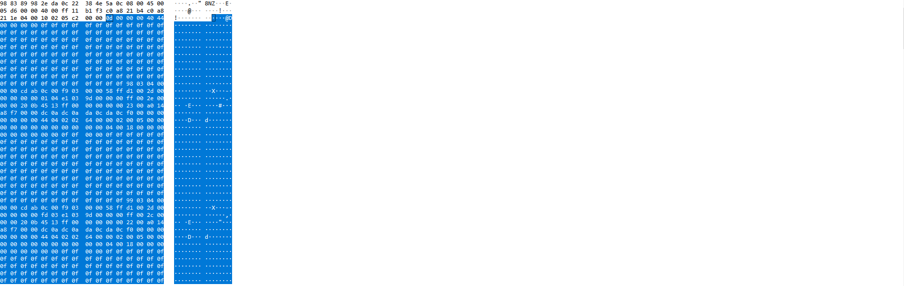
However, with monitoring using Wireshark, I could not find and data that i wrote on LVDSStreamSwConfig.

What part do i miss to capture user data through lvds and ethernet communication using AWR1642 and DCA1000?

Thanks a lot

Jinhyeong Kim

  • Hi Jinhyeong ,
    Are you able to capture correct user data with the default application (mmw demo)?

    Regards,
    Jitendra
  •  This is the output when i use default code in mmw demo file..

    I could not confirm that this is the right file..

  • Hi,
    Inn the modified code, create that data buffer as global not local to function as actual LVDS transmission happends using eDMA and triggers after this function returns.
    If you are enabling HSI header then it will add prefix of some bytes (including 0x0F0F) then adds up the user data.

    I'll provide the exact captured data format soon. Meanwhile make those buffer as global variable and retain the LVDSUserDataHeader to userBufferInfo[0] and add new global buffer to userBufferInfo[1]


    sessionCfg.u.swCfg.userBufferInfo[0].size = HSIHeader_toCBUFFUnits(sizeof(MmwDemo_LVDSUserDataHeader_t));
    sessionCfg.u.swCfg.userBufferInfo[0].address = (uint32_t)&(streamMcb->userDataHeader);

    sessionCfg.u.swCfg.userBufferInfo[1].size = HSIHeader_toCBUFFUnits(sizeof(buff_data1));//(datPathObj->numDetObj) * sizeof(MmwDemo_detectedObj));
    sessionCfg.u.swCfg.userBufferInfo[1].address = (uint32_t)buff_data1;//datPathObj->detObj2D;


    Regards,
    Jitendra
  • Thanks a lot!! When change variable to global variable, I could see data through wireshark.

    I have two more question

    1. When I add one more data such as userBufferInfo[2], the demo file doesn't run after command configuration file to AWR1642.
    Is there any limitation to send only one user data? And is there any limitation of the size of user sw data to lvds?

    2. When I configure DCA1000EVM through Lua command, I could select Capture mode via ar1.CaptureCardConfig_Mode_WithoutSPI()
    At the first of this function, it means eLogMode. So when i put 1 to that part, it means Raw mode, and 2 means Multimode

    When using DCA with 1, it transmits maybe 1466 bytes via ethernet, while with 2 it transmits 266 bytes. With former one, user sw config data is located at the end of the packet. And with the other, sw config data is located and repeated among the entire packet. Which is more useful, if I just want to transmit user sw data through lvds and ethernet with high speed?


    Regards
    Jinhyeong
  • And one more question is when will the exact capture data format provided?

    Thanks a lot

    Regards,
    Jinhyeong
  • For Q1, refer to e2e.ti.com/.../2915279 . The size limitation per buffer is 0x3FFF CBUFF units (1 unit = 16-bits). The CBUFF driver allows up to 3 buffers [which means Info[2] is o.k] but the oob demo's EDMA allocator for software session (MmwDemo_LVDSStream_EDMAInit) is only assuming two, so if you want to send info[2], this code needs to be updated to add available EDMA resources for the 3rd buffer (gMmwDssMCB.lvdsStream.swSessionEDMAChannelTable[2].* = ..).

    Without the above change, the allocator will return an error to CBUFF during CBUFF session creation when it attempts to ask for resources for the 3rd buffer, and the session creation will have returned the error and the error code would have been printed out on the CCS console.