This thread has been locked.

If you have a related question, please click the "Ask a related question" button in the top right corner. The newly created question will be automatically linked to this question.

PGA411-Q1: SPI_ERR fault 0x1 - SPI CRC Error

Part Number: PGA411-Q1

Hello,

I have recently configured an STM32L432 processor to communicate with the PGA411 IC via SPI to get angle information from a resolver. With the FAULTRES pin held low, I am able to receive angle information, write and read to registers, and unlock and save data to the EEPROM.

Now to the point where I would like to troubleshoot any other PGA411 faults, I have set the FAULTRES pin high. All system functions appear to be operating fault free, including SPI register writes, except for when I perform a SPI register read. Every attempt at reading a register, I receive a SPI_ERR fault of 0x1, which is an an invalid CRC or SPI clock. The interesting thing is that I do always receive the correct data from the registers when reading.

Does anyone have any ideas for what could be causing an error like this? For example, a simple read process of mine for OVUV1 looks like this:

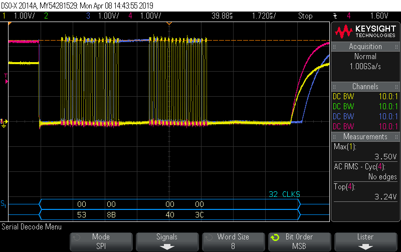
- Set transmit data to be written to 0x5300000B. Read address = 0x53, dummy data = 0x0000, CRC-6 = 0x0B

- Transmit data over SPI

- Second transmit over SPI, same data, sent 50us later

- Store received data

There is no specification for what the dummy data contents are correct? Do any OVUVx registers require the device to be in diagnostic mode to read?

Let me know if there is any other information I can supply that could help diagnose this.

Thank you

  • Can you share a waveform of the SPI read?

    Also, this app note includes some SPI debugging tips for the PGA411-Q1:

    www.ti.com/.../slaa688.pdf
  • No problem, screen shots below. I could only get a probe on 3 of the SPI lines(MOSI excluded).

    Yellow - SPI clock(First time I noticed the amplitude difference at the beginning and end of each transmission)

    Blue - SPI MISO

    Pink - SPI CS/NSS

    This was 2 simultaneous read requests to read register DEV_OVUV1. Message from master is 0x5300000B. This scope has a serial decoder, so the blue boxes at the bottom are the decoded SPI frames. The bottom line is what was received from the PGA411. 8B 40 is the correct data programmed in that register.

    This image is a zoomed in version of the second read request. Still a bit hard to see, I could send a closer image if desired. There are 32 clock pulses.

  • Hello Clancy,

    Does anything I have shown point to a reason for receiving the SPI error? I am continuing to receive this error although still appear to be reading the correct values upon each read. Let me know if any other information would be helpful.

    Any assistance would be appreciated.

    Thanks
  • The amplitude difference of the SPI clock is strange. However, since the signal appears valid while NCS is low, I doubt that it is the problem.

    I noticed that you are sending the same message two times in a row except for bit 6.

    53 8B 40 7C
    53 8B 40 3C

    Bits 6 and 7 are supposed to be reserved as 0 as seen in figure 41 of the datasheet. Perhaps that is causing the issue?
  • Clancy,

    I was unable to probe the SDI pin, so the transmit message from the MCU is not pictured. The message 0x5300000B was sent 2 times, and those screen shots are the responses from those 2 messages.

    As you mentioned, the bits that are different between those 2 messages are the SPI status bits. It appears that the message 0x01(SPI CRC error) was received in the first message, and 0x00 was received in the second. I'm guessing either the error only appears in the first message attempt, or the status bit becomes invalid after a SPI error is detected.

    Is message 0x5300000B correct for reading the DEV_OVUV1 register? The read example in the "Step-by-Step Initialization" document sends a dummy data value of 0x00F0 instead of 0x0000, is there any requirement to the value that is sent as dummy data?

    I also see that there is a configuration CRC based on the values stored in EEPROM. Does this value need be used instead of the normal CRC-6 value used when performing a write? My value of 0x0B is the CRC-6 of 0x530000.

  • Your message values look correct. I'm wondering if the problem is with the SCLK line. Note that SDO is not released until NCS has crossed the logic high value. SCLK, which is controlled by the MCU, is being released at the same time as NCS.

    Normally SCLK is low between SPI frames. Is there a way to configure your MCU to do that?
  • Clancy,

    Thank you for the follow up. Unfortunately I had to send my board out as a sample so I do not have one to test at the moment. Once I receive a new one, I will look into your suggestion.

    The MCU SPI configuration is set up with a clock polarity of 0, so I would also expect the clock signal to be low between messages. Something to look into.

    Thanks.
  • No problem, I will close this thread for now, but please reply or start a new thread when you get an update.