This thread has been locked.

If you have a related question, please click the "Ask a related question" button in the top right corner. The newly created question will be automatically linked to this question.

FDC2114EVM: Measurement of a person presence at 10 to 50mm distance with FDC2114

Part Number: FDC2114EVM
Other Parts Discussed in Thread: FDC2112, , FDC2114

Hi,

I would like to use a capacitance sensor for detection of a person present at a distance of 10 to 50mm.

FDC2112/14 seemed to be a good solutoin, so I ordered the Evaluation Board.

For the first tests I use a round aluminum foil cutout of 200mm diameter (314square centimeters). It is connected to the channel 3 of the FDC2114EVM with a coax cable in single-ended configuration.

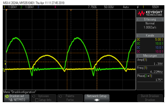
I could optimize sensitivity of my configuration by lowering the capacitance of the LC-tank to 4.7pF.  But when I set the LC drive current (IDRIVE) to achieve 1.2V to 1.8V oscillation amplitude the sensitivity is goes down . Otherwise, when I reduce the LC drive current to 60uA and lower I can detect a much higher signal. How can that be? Are there some configurations I missed?

Thank you.

E.P.

  • Hi E.P.,

    Are you saying that if you reduce your drive current so that the sensor oscillation amplitude is below 1.2V you receive a larger output code shift when your target is present? It would be helpful if you could provide scope captures of the oscillation amplitude (probed at both INxA and INxB vs GND) when your system is most sensitive. It would also be helpful if you could provide more detailed information about the "much higher signal" you can detect. Screen shots of the Data Streaming page of the GUI would be fine.

    Best Regards,
  • Hello Kristin,

    thank you for your reply.

    Kristin Jones93 said:
    Are you saying that if you reduce your drive current so that the sensor oscillation amplitude is below 1.2V you receive a larger output code shift when your target is present?

    Yes, thats correct.

    Here is the scope capture for the specified configuration of the system (IDRIVE: Code = 25 / Current = 644uA , Measurend Amplitude = 1,39V, Channel 1 (yellow): IN3A, Channel 2 (green): IN3B). The sensor probe is connected to IN3A of the Eval Board:

    And here is the scope capture for most sensitive configuration of the system (IDRIVE: Code = 9 / Current = 60uA , Measured Amplitude = 280mV, Channel 1 (yellow): IN3A, Channel 2 (green): IN3B). The sensor probe is connected to IN3A of the Eval Board:

    And here are the results for different current settings (60uA and 644uA). Raw code changes were observed for the sensor plate on the table and a hand in proximity through the table board (20mm).

    1A) IDRIVE Code = 25 / Current = 644uA, GAIN = 8, RCOUNT = 0xffff, no hand in proximity:

    1B) IDRIVE Code = 25 / Current = 644uA, GAIN = 8, RCOUNT = 0xffff, hand in proximity through the table board:

    2A) IDRIVE Code = 9 / Current = 60uA, GAIN = 8, RCOUNT = 0xffff, no hand in proximity:

    2B) IDRIVE Code = 9 / Current = 60uA, GAIN = 8, RCOUNT = 0xffff, hand in proximity through the table board:

    For higher drive current  1A) and 1B) the delta between the raw code  is only 132, whereas I get max. sensitivity at drive current of 60uA with delta between 2A) and 2B) of  243.

     So the signal change seems to be much higher at a lower current. Is there anything I overlook?

    Thanks.

    E.P.

  • Hi E.P.,

    Thank you for sharing the scope captures. They are very helpful, and I think I see your problem. Your oscillation amplitudes on IN3A and IN3B are unbalanced, so I assume you have connected your aluminum foil sensor to IN3A only. This will significantly increase the capacitance for only half of the oscillation period; during the other half the aluminum foil sensor will be grounded on both sides. This increase in capacitance will significantly decrease the Rp of the sensor during half of the oscillation period, which will in turn require more drive current to keep the oscillation amplitude between 1.2-1.8V. The problem is that this increased drive current will be too much for the other half of the oscillation period, driving the oscillation amplitude far above the 1.8V maximum. The oscillation amplitude needs to be between 1.2-1.8V for both INxA and INxB, and ideally they should have the same amplitude.

    In your case, when IN3A is at 1.39V, IN3B is at ~3.2V. This is extremely close to the absolute maximum voltage on any pin (VDD + 0.3V), and the ESD diodes are likely starting to turn on, which will significantly impact your measurement accuracy. Prolonged operation at this voltage may impact the device's reliability, as the absolute maximum ratings are stress tests only. When you reduce the drive current, you are likely seeing an improvement in SNR because the ESD diodes are not affecting your measurements.

    To solve this issue, I suggest using a differential measurement. You can do this simply by cutting your aluminum foil sensor in half and connecting one side to INxA and the other side to INxB. Then you should have roughly even amplitudes and should be able to set your drive current so that the amplitude is correct for the full oscillation period. If you want further information about setting the drive current, the drivers of the LDC131x/LDC161x devices are similar to the FDC2114, and this app note should help: www.ti.com/.../snoa950.pdf

    Best Regards,
  • Dear Kristin,

    thank you very much for your reply. Now I understand what is going on in my sensor design and the application note that you shared was very helpful.

    However, I have one more question.

    In the datasheet of FDC there are two configurations described in chapter 10.1.1: single-ended and differential sensor configuration. But, there is nothing said about balancing single-ended configuration. Also, the single-ended configuration is said to have a higher sensing range than the differential configuration. Since for my application a sensing range of up to 50mm and only single sensor area with single cable is requered, I would prefer to go with the single-ended configuration. So the question is, if it is possible to balance my sensor with an additional SMD-capacitor on IN3B with the capasitance of the aluminum foil sensor, instead of dividing it in two sensor areas?

    Thank you in advance.

    E.P.

  • Hi E.P.,

    My apologies that there is no warning about unbalanced sensor oscillation amplitudes in the datasheet. This is planned for future datasheet revisions.

    You may experiment with adding additional capacitance in parallel with the existing capacitor in your LC tank. If you add enough such that the additional capacitance from the sensor plate is not a huge deviation from the capacitance in the LC tank, you may have an easier time balancing your oscillation amplitudes.

    Also note that the single-ended configuration is not inherently more sensitive than the differential configuration. This is only true if the single-ended sensor is the same area as the combination of the two differential sensors. If you sized both differential sensors to be the same size as the single-ended sensor, the differential configuration would be at least as sensitive as the single-ended configuration. You have quite a large sensor already, so you likely have room to use half for each side of the differential configuration.

    If you have not seen it already, this application note about proximity sensing using the FDC2x1y devices should be helpful to you: www.ti.com/.../snoa940a.pdf

    Best Regards,